This is a blog post detailing my construction of a thermometer, from the planning phase, to parts choice, to construction and to final results. It’s split in subchapters and contains a lot of helpful advice, plot twists and fun facts learned along the way. The finished product turned out to be of high quality, meaning that despite the few mistakes and changes in the plan along the way, persistence and planning won out in the end.
The idea
I’m constantly looking at building projects which I can apply and use in my daily life. Usually some sort of gadget, something for fun, that’d generate a slight chuckle when with friends or alone. Recently I’d been tired after school and needed something easy to knock out, while simultaneously having something I could use. I usually build such projects, where the code and libraries can be recycled and added to other projects. Eventually I’d have exponential growth where I’d have already done a library for something and I’d just need to attach it on top of some other code. To this end I came up with the idea of building a thermometer. Just a simple one, to measure the temperature in my room and display it. How hard could that be?!
Scope creep, defeats and victories
Initially I wanted to have a device that would measure the ambient temperature, ambient humidity, and ambient light level, then log all of that to an EEPROM while simultaneously displaying it. It would also keep accurate track of time, and give an average statistic for all of the values it measures for the day and for the week. Ideally, this would be available on a web portal that I could access through WiFi anywhere from home. However, as it turns out, ideas that ambitious are hard to implement when exhausted after school every day. First of all, I couldn’t think of a microcontroller that would contain all of those capabilities on one board or chip. Here is how I progressively dealt with scope creep, and had some defeats on my own along the way.
Using an ESP8266 would give me WiFi, a powerful main processor with almost limitless memory, and the availability of also limitless Arduino libraries. On the other hand, it would mean ending up with one analog pin with a limited range, meaning I’d have to use an analog multiplexer chip. Since the analog pin on the board uses a voltage divider, any analog sensors (of which I planned on using multiple) would have to have an operational amplifier buffer. Even more annoyingly, every time I tried to use an EEPROM or flash chip, the watchdog would kick in and reset my ESP, even when I tried an ESP32. Any attempts to Google my way through the problem and defeat the watchdog ended up in failure, so I decided to move on to a different board.
Next I tried a regular Arduino, which meant I could still use the limitless Arduino libraries I had hoped to use. I obtained a standard DHT11 temperature and humidity sensor, immediately connected it to the Arduino, used a common Adafruit library, and after only five minutes it worked! Printing the results through serial gave a beautifully formatted output which reacted to me blowing on the sensor and holding it in my hand as I’d expected it to. Yes, nominally the DHT11 did have an apparently low accuracy of 5% and a low range of output readings, however I didn’t need an exact result, nor did I plan on measuring hundreds of degrees Celsius. I accepted the sensor and its eccentricities, and it appeared as if I had won, and my simple relaxing project would end up being a simple one-day deal. Immediately after, I connected an SSD1306 display in order to do the second part of my plan, which is to display the results on something that displays. I hoped to use the same print function present on the serial port to just print on the screen. The code compiled well, uploaded, and on the screen I was greeted with a… question mark… Apparently the library did not like my floats, or my ways to try and convert a float into a string, or char array, or any other attempts short of typecasting everything to hell and back. After about half an hour, I admitted defeat on my own terms. I didn’t like the SSD1306 display anyway.
Back to the drawing board
Since the majority of my issues came as a result of me fruitlessly trying to coalesce libraries into doing something they didn’t want to, I decided to continue the project in a much more DIY fashion. I’d write the code for all the libraries myself, design the circuit, use as few modules as necessary, and finally, I’d drastically reduce the scope of the project. The measurement of light appears to be extremely complicated, and I have neither the background knowledge necessary, nor the calibration equipment, nor any lenses, nor any good accurate sensors, and finally I didn’t know what exactly I was measuring. Not good for metrology equipment, even despite my acceptance of the low accuracy of DIY measurement. I decided to remove the humidity requirement as well, since not only is the DHT11 sensor notoriously inaccurate when measuring humidity, I also don’t even know what to do with the humidity information, especially inaccurate one. Thus the DHT11 was out of the game and I’d look for a new sensor, however first I needed to slim down the project even more. Realistically I had no time to do the necessary calculations and testing to implement logging and statistics well. I had no experience and no time to get the experience, meaning that that part would also have to go. I was finally just left with temperature and a way to display it, which is where I believe that the cutting down of requirements proved to be an excellent benefit to my completion of the project.
It appeared that the measurement of temperature electronically was also a difficult and interesting subject by itself to tackle. There were many solutions on the internet, from dedicated sensors, to thermistor voltage dividers, to using different effects that temperature has on metals to generate and measure differential voltages. Some even went with the simple idea of not even measuring ambient temperature, rather using a WiFi-enabled board and contacting a server which held information about the local weather in every city around the world. These all seemed like fine ideas, however I decided I wanted to work a bit in the analog world and look into how ADCs (analog-to-digital converters) work. For this purpose, I found a cheap PIC microcontroller, which I decided would be the brains behind the whole project. The exact model is PIC16F1705, which I chose because of the convenient DIP-14 package, excellent analog capabilities, large number of peripherals, and most importantly, local availability.
Most of my projects are unfortunately limited by the availability, or lack thereof, of parts locally. The vast majority of online retailers don’t ship here (Macedonia) and the ones who do charge exorbitant prices for shipping of even the smallest and cheapest of goods. The parts availability here is limited to three moderately stocked electronics stores, all of which charge quite high prices for parts, and still have limited selection themselves. Thus I had to keep that in mind when designing a parts list and planning out the full range of capabilities of my project. However, in this case, that didn’t appear to be as big of an issue as it is other times, with more ambitious projects, which was quite convenient.
The PIC16F1705 appeared to be ideal, with a low price and a powerful peripheral set, while being relatively snappy at 32MHz itself (8MHz ATMega equivalent). With 8KB of flash and 1KB of RAM, I had no doubts that this microcontroller could measure and keep temperature. Furthermore, these new PIC microcontrollers have an extremely powerful and internally interconnected peripheral set. My main draw behind this PIC is the advertised Advanced Analog features, which I wanted to test out for myself, as having a microcontroller that even has operational amplifiers built in seemed like a steal, and I’d really have bought it solely for that, but Microchip just keeps on giving.
Feeling the heat
Now that I had the microcontroller, the brains, picked out, I had to look at how I would actually measure the temperature. The PIC microcontroller, like with many others of the newer PIC models, actually has a temperature sensor built in. Yes, built in, inside of the microcontroller. Theoretically I could have this be a one-chip project, and have a single little chip replace what would have been an entire board in the past. This was truly wonderful, however I decided to add the requirement of the temperature sensing part to be something more mobile, so that if I wanted to I could measure the temperature of something quite hot, which would mean that the sensor would have to extend somehow. I didn’t want to have some strange solution where I’d touch the microcontroller to something very hot, and I also wanted a challenge, so I decided to go for a dedicated solution.
Having discounted doing the measurement internally, I decided to look for something that was cheap, available, and could measure temperature. The options were then to either use a thermistor or a dedicated temperature sensor IC. The thermistor idea seemed more attractive, as I already had two thermistors already. I wired up one of the thermistors, which stated 50Kohm of resistance (at room temperature) and in my room, which is at approximately room temperature, it gave 50Kohm of resistance. While that was lovely, I quickly realized that the thermistor solution was infeasible and for me, or realistically, impossible. This was due to the fact that even though I knew that for 25C I’d get 50Kohm, I couldn’t reliably measure at any other temperature at all. The only equipment I had for measuring temperature is an old mercury thermometer, which is labeled in a way that makes it hard to even see the exact temperature, not including labeling errors, which would mean that my result would be wildly inaccurate. Adding on top of this would be any nonlinearities of the thermistor. However, I’d need another measurement point in order to create a linear equation to extrapolate the temperature from resistance. This impossible task meant that unless I wanted to continue using the DHT11, I’d have to look for a different solution.
While browsing for different analog sensors, I found that the store I had been buying my Microchip PICs from also sold Microchip analog sensors, one of which was the MCP9700 series of thermistors, which for a given input voltage of approximately 5V would give a quite accurate output voltage, which could even be characterized and measured to obtain extremely accurate results. Even better, unless I wanted extreme accuracy, the temperature could be approximated using only a simple linear formula, which with some rearranging can be made into an integer-only formula, ideal for my 8-bit PIC16F1705 with only 8-bit add and subtract. The sensor, due to it being in the TO-92 package, could be connected with a few long wires and used to measure specific items. To add on top of all that, it required no additional external components. While the uncalibrated accuracy of the sensors is quite poor (±4V), the many graphs Microchip provided made me confident that in my range of approximately room temperature, the MCP9701 (the sensor I chose due to its superior 5V performance) would be just fine, and it appeared as if the most accurate measurements were concentrated in that area. Now that I had my microcontroller and temperature sensor selected, I ordered them, and since I live in a small country, got them delivered the next day by a postman who was quite lost.
Formulas and math
Once I had the required components I quickly figured out a schematic which was essentially just connecting the MCP9701 sensor to the PIC16F1705’s ADC. I first wanted to handle the temperature sensor output, since even if I was unsure how I would display it, having the sensor be able to read out temperature and send it out through some communication protocol is useful by itself. I first settled with using a UART as my protocol of choice for communication. For the programming I used MPLAB X and took advantage of Microchip’s wonderful tool MCC, which is simply one of Microchip’s many code generation tools. Despite not supporting older PICs, the newer PIC16F1705 was fully supported and all peripherals were available to be set up and used in detail. One part I particularly like about MCC is the ability to reroute STDIO to UART, enabling the use of C printf functions and all the assorted formatting that comes with them. While this comes with a somewhat large code size penalty, I found that the XC8 compiler only compiles printf for the types it knows will be printed. In the end, the full code ended up being slightly larger than 1KB, out of 8KB total available, so using printf for outputting values and debugging would not prove to be an issue. I set the UART at a conservative 9600, for which MCC automatically calculated and set all the registers, and connected it to an Arduino Uno set up as a UART bridge (my FT232RL module is currently not working). I sent a Hello World message, and it arrived perfectly. Once I knew I had working printf debugging and could send data back and forth from the PIC16F1705, I could begin with programming the analog-to-digital conversion.
The PIC16F1705’s main selling point is that it has advanced analog features, and in this case those came to be invaluable. I first began with setting up the ADC peripheral in MCC, and was truly surprised with the freedom MCC gave me to set up the peripheral. The most valuable part of the setup, though, was the FVR peripheral, which is a fixed voltage reference built into the PIC with three possible voltages (1.024V, 2.048V and 4.096V) which acts exactly like a regular voltage reference. One of the big selling points of the PIC16F1705 is the ability to use it to build clever buck/boost converters and this is one of the useful parts which enables anyone to heavily integrate their design all into one chip. However, in this case, I could use the FVR as a reference for the ADC. It was here where the peculiarities of the temperature sensor I was using and this combination of the microcontroller’s capabilities could join together and create something excellent.
I first looked at the datasheet of the MCP9701 and saw that its voltage output is quite linear, particularly around the temperature ranges I was measuring (room temperature, ~20C). Even though the voltage output could more accurately be modeled as a second order polynomial, if lower accuracy is satisfactory then a simple linear formula is given in the form that anyone who has passed algebra in high school would know – y = mx + b. It was here where I became happy that I could finally do some math, as often with microcontroller projects it’s just figuring out how to interconnect libraries or interface to different peripherals, rather than doing any sort of math. The formula given was:
V_{out} = T_c * T_a + V_{0c}where Vout is the output of the thermistor IC, Tc is the temperature coefficient (in millivolts per degree Celsius), Ta is the ambient temperature (in Celsius) and V0c was the voltage at zero degrees, essentially the x-intercept of the linear formula. Rearranging for ambient temperature gives:
T_a = \frac{V_{out} - V_{0c}}{T_c}The datasheet gave the needed values for V0c and Tc for the MCP9701 which were 400mV and 19.5mV/C respectively. It was here where I reached an interesting problem. Usually when working with 8-bit microcontrollers, particularly ones like PICs which don’t even have a hardware multiplier, much less a floating point unit, one exclusively uses 8- or 16-bit integers for code. However, Microchip provides quite decent floating point libraries for even the 8-bit PICs, so I had to choose whether to continue with integers, which would be faster, take up less memory, however with the downside of having more code which is less readable. Initially, I chose the integer route, then once I was done and satisfied with the code I also rewrote it with floating point variables, which worked very well and was surprisingly fast.
However, at first I decided to go with the integer version. The issue in the original formula is that the temperature coefficient is a number with a decimal, which by definition is not an integer. The solution to this was easy, just multiplying both the numerator and denominator by 2, to get a fully integer formula. This resulted in the formula:
\frac{2V_{out} - 800}{39}Unfortunately in this formula there is division between integers, which would naturally result in a significant loss of accuracy, and the ways I dealt with that will be described later. However, for now, I went on with determining how I could get the most accuracy out of my ADC result.
Consulting the datasheet of the MCP9701, as mentioned previously, I saw that the results in the temperatures I was going to be using were all concentrated in a lower voltage region. This meant that I could use the FVR peripheral as a reference to the ADC to enable a more accurate ADC measurement at lower voltages. To illustrate, the 10-bit ADC of the PIC16F1705 normally uses the microcontroller’s input voltage as a reference. This means that any analog voltage that’s input is measured to the main system voltage. With a 10-bit ADC this means that 1024 different outputs are possible. The result of the ADC is then basically a proportion. For example, if 3V are input into a 5V system, the proportion is 3/5, or for a 10-bit ADC:
\frac{3}{5} * 1024 = 614From this it is also possible to calculate the highest precision the ADC is capable of measuring. With a 5V reference, this would be:
\frac{5}{1024} ≈ 0.005V = 5mVThis is a really high accuracy for most purposes, and in this case the number can directly be used to see how accurate the measurement in degrees from the sensor would be. If the sensor has a coefficient of 19.5mV per degree Celsius, and the greatest accuracy measurable is 5mV, then the greatest accuracy in Celsius measurable is:
\frac{5}{19.5} ≈ 0.25CAgain, for most purposes this is excellent, and most people would not benefit from a more accurate measurement for their room temperature, however I was determined to get more.
Using the fixed voltage reference as the ADC reference, we can recalculate the accuracy of the measurement. I chose 2.048V as the reference since it enabled an acceptable range that would cover all possible temperatures in my room, while still being accurate enough. That accuracy can be calculated with:
\frac{2.048}{1024} ≈ 0.002V = 2mVThis is much more accurate than the previous measurement with the reference, and recalculating with the temperature coefficient gives an accuracy of:
\frac{2}{19.5} ≈ 0.1CThis means that I could have one full significant digit of accuracy without sacrificing temperature range. Now I could get an equation that would take into account the result from the ADC and scale it properly to get a final formula to put into the microcontroller. This equation is:
\frac{2V_{out} - 800}{39} = \frac{2 * \frac{V_{in}}{1024} * 2048 - 800}{39} = \frac{2 * 2V_{in} - 800}{39} = \frac{4V_{in} - 800}{39}Now I could begin programming.
Happiness at first result
I first decided to check if the ADC was properly working. The ADC gave a 10-bit result in the form of a 16-bit unsigned integer. Initially, I looked for a way to convert a 16-bit unsigned integer into a BCD char array suitable for sending through UART. I knew that I could print it with printf, however in the cases that I couldn’t I wanted to find a decent routine that I knew worked. I knew how to write one on a PC, with comparatively endless RAM and processor cycles, however on a PIC this would be more difficult, and I began looking on the internet for some methods to do this. I found an excellent method, interestingly enough, on the Microchip forums. Creating a small buffer for storing the digits and writing a routine to print out the result from the ADC, I compiled and uploaded the code to the PIC and connected my Arduino patiently. After the 1 second delay I introduced, I saw my first numerical result from the ADC. I never wrote it down, however I still remember my first result. The ADC reading said – 434. I grabbed my TI-84 Plus CE graphing calculator, an invaluable tool in electronics as I’ve found, and input the formula:
\frac{4*434 - 800}{39}The result it gave back was a nice, round 24 degrees Celsius. That day my room was quite warm, and my mercury temperature sensor appeared to support this result. I was ecstatic!
I then went to implement the whole formula in the microcontroller, inputting it as I did in the calculator, connected it to UART and it gave out a steady stream of whole-number temperatures. I was also happy at this, and the temperatures appeared to be very much in accordance with the mercury thermometer I had. Furthermore, to test if this was not a coincidence and I was just seeing random analog signals the ADC was detecting or the sensor was stuck, I did the classic test of holding the sensor between my fingers. In the course of approximately 10 seconds, the output reached around 30C. This surprised me as I’m known to have cold hands, however as I said, it was a hot day. These results may have been okay and I could have ended it here, however I didn’t want my advanced analog capabilities and 0.1C precision to go to waste. Thus I decided to continue my quest for even more accuracy.
The solution I came up with was simple. If I took the whole number result I got and multiplied it by 10, and then subtracted it from the original ADC reading formula multiplied by 10, I could get the missing significant digit I wanted. While that resulted in horrific code for an 8-bit microcontroller, I was fine with this since the microcontroller had no other job. I could afford a long processing time as long as it gave a decent result. I updated the code, did some fun formatting to make the output appear nicer, even including a decimal digit and a letter C! The resulting program appeared to work excellently, and I could finally move on to the display. Or could I…
As I found out, the reading was quite unstable and would jump randomly to ±1C. This was terrible and I never got to fixing the issue, just mitigating it. To power the PIC I used a simple USB connector with a breakout board. Since USB is nominally 5V, this is usually fine for the vast majority of circuits. However, in this case, I was using an analog circuit, which meant that the extremely noisy USB 5V would be the worst case scenario to use as a voltage in an analog circuit. Adding capacitors somewhat removed the problem, however it was still there. USB is inherently noisy due to the voltage coming from an environment where there are literally billions of tiny transistors switching billions of times per second, and a few massive power transistors switching thousands of times per second. This means that the noise is also horrendous and USB is bad for any kinds of sensitive analog or audio circuits. In this case, since I like the simplicity of the USB port as a power delivery mechanism, I decided to just go with it and accept the noise, which was somewhat mitigated with the addition of capacitors.
To further mitigate the issue, I decided to go with a slightly more complicated approach regarding the temperature measurements. I would still measure as normal, however I would measure 10 points of the temperature, 1 second apart each, and then output the average from all the 10 seconds. This would mean that the influence of any particularly nasty spikes would be damped by the other 9 results, which are statistically more likely to be normal. This proved to be a good choice, as when combined with the capacitors, the result was more stable than it previously was. However, I still believe that more sampling is needed, and that the update rate of once per 10 seconds is also too fast for a temperature sensor. In the next revision, I’ll attempt an update rate of once per 60 seconds (1 minute) to be more appropriate for a room temperature sensor. However, for now I am quite satisfied with the readings and results and they are almost always supported by my mercury thermometer, usually to a ±0.5C range, which I find satisfactory. Now that I had my measurements work well and be accurate, it was time to move on to actually displaying them on something other than a UART, through an Arduino, then to a computer. I wanted to be able to just power it on and look at the result, which naturally led me to look for a display.
Finding a display
Looking for a display appeared to be quite harder than I initially thought. This was not due to lack of choices, rather the total opposite. In my different sorting bins I had all kinds of displays, from small 0.96inch monochrome 128×64 displays, to 7 segment displays with varying kinds of controllers, to even large 4inch displays with full color graphics and high speed SPI interfaces. Initially I believed that I would use the 128×64 displays as they were the ideal blend between simplicity in communication (just I2C) and capability (128×64 gives a surprising amount of detail. The display in question is a generic cheap Aliexpress display with the SSD1306 display controller that comes in both I2C and SPI varieties, and is very capable given the limited screen size and resolution it has. It’s an OLED display, meaning that the contrast is excellent, so naturally I chose this as the display that would show the temperatures measured.
The display of the kind I chose is I2C and since the displays cost less than 2$ with shipping included, I had a sizable amount and a decent variety of colors to choose from. I chose blue, since it appeared to have the highest visibility from distance when I tested it with an Arduino. Visibility was mostly my main priority with the display, as the only other requirements were the ability to display 3 digits, a dot and the letter C, and the ability to update faster than 0.1Hz. Essentially all displays I have met the other requirements, which only left visibility. Using an Arduino to test it naturally meant that I was limited to the Arduino ecosystem, and going outside of it necessitated writing my own library for the SSD1306. I used the MSSP peripheral in MCC to quickly generate an I2C signal for communication, however I now had to look at all the setup registers for the SSD1306, which I found a list of in the datasheet and quickly verified online. Unfortunately, even though I was able to write to the setup registers of the SSD1306, the I2C communication seemed to only intermittently work.
Further developing my own library I was able to get character output, however I was never able to fix the issue of the intermittent setup, and I had to resort to resetting the system a couple of times for each time I wanted to turn it on. Furthermore, even when making the digits as large as possible, I was never able to get decent visibility in light. I had displays in yellow, blue and white, all on a black background, but still none seemed to work that well. I had issues in being able to see the digits from afar, which combined with the issue of the intermittent startup led me to abandon the SSD1306 display idea. To make matters worse, if I wanted to buffer the display in the PIC RAM to do any kinds of interesting graphics, I’d need 1KB of RAM, which is exactly how much the PIC has. This would mean that I’d have to use some extremely clever code and save temporary data in unused configuration registers, or just not do buffering at all. Since just using the SSD1306 display to show 3 digits, a dot and a letter seemed like overkill, I looked to the next best alternative.
The fancier SPI displays with full color were overkill and the same buffer issue would arise, which only really left me with the 7 segment display options. The option of the 7 segment displays turned out to be an interesting design contest by itself. By using such displays, with 4 digits, I would be able to show all the data needed, including the two digit whole number for the temperature, the decimal dot, the one decimal digit, and the C for Celsius. I already had an interesting circuit created which uses a register file, an oscillator, a counter and a BCD to 7 segment decoder to hold number data and display it efficiently, requiring zero processor power, however that seemed overkill and also I would not be able to display the letter C. The PIC16F1705 has only 11 IO pins, and I’d already used one for the ADC, meaning that I’d have to creatively use the other pins as well. One idea that came to mind instantly was using a 2-to-4 decoder for the common anode display, and displaying the digits directly from a digital IO port, which would practically use up all of the pins available, however I know that it would work. However, this would then require a lot of resistors and the addition of a 74HC139 logic chip, which itself would only be partly used, and would greatly expand the list of required materials, which I wasn’t keen on.
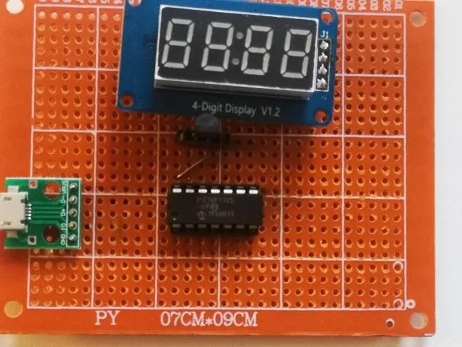
This left me with only the 7 segment displays which had some sort of external controller, of which I only had one, a display with the common TM1637 chip which is able to interface both to a 7 segment display and a keyboard at once. The TM1637 was part of a generic Aliexpress module whose total cost usually comes out to approximately 80 cents with shipping included, which is ideal for getting in bulk for all kinds of projects. This also meant that I could be confident in getting as many as I needed if I wanted to build more of these circuits. With the three main parts of the circuit, the total cost came out to be approximately equivalent to 4$, which I was very satisfied with. As two out of the three parts were local parts, with inflated prices, the real cost would likely come out to be lower.
Once I had chosen the final display with the display chip, the next task became to write the library that would communicate with the chip. Unfortunately, even though the TM1637’s interface is very similar to I2C, it differs in enough ways to make it incompatible. Due to this, I had to bit-bang the communication protocol. However, due to the wide availability of the TM1637, the protocol was well-documented and explained online. Usually I’d attempt to decode it from the datasheet, but in this case the datasheet was available either in Chinese or automatically translated English, which was a significant difficulty in figuring out the protocol’s workings. Still, on the internet I found many examples of libraries used for communication. Most of those were written for Arduinos, so I necessarily had to translate them to work with PIC microcontrollers, however I was confident that this task would only require replacing mostly digitalRead, digitalWrite and pinMode functions.
Since there were many libraries, I had to choose, so I went with the most popular library for Arduino. I decided to only copy the functions that I’d need, which in this case were only functions that are for writing digits, without any sort of decimal to BCD conversion or similar formatting. The source code for this library, however, appeared very strange at first sight. There were only pinMode function calls, and only two digitalWrite functions in the beginning. This stumped me for a while, until I realized that the TM1637 protocol is similar enough to I2C to be similar in physical signaling. Namely, the pinMode is essentially used as the digitalWrite. If the pin is output mode, then the pullup resistor is connected to ground and that signals a zero. If the pin is in input mode, then it is in high impedance and the pullup resistor will signal a one. This is quite a nice way to do bus-contention free signaling, however I don’t know why the TM1637 didn’t opt for pure I2C, as its protocol doesn’t enable easy access to multiple TM1637. Maybe the company that made it didn’t want to pay the associated fees for an address.
Still, I ported the Arduino library and cut it down to its bare necessities. I’d need to format my own output string in my custom way anyway, so any other library functions other than direct digit access had to go. In this process I made a mistake in the form of forgetting that since I was porting a library from C++ to C, there were some sacrifices I’d have to make, and foregoing classes was one of them. For some time I was confused why classes wouldn’t work in the XC8 compiler, until I realized I was stuck with an ancient C standard. Luckily, the porting barely took half an hour until I was perfectly satisfied with the cut-down version of the library. One benefit of using this library was that it had a table of all hexadecimal digits and characters that I would want to display, which made development much smoother. Once I was satisfied with the functions I had, I wrote some test code that would just display 1234, and to my amazement, it worked on the first try.
Once I had this done, it was only a matter of properly copying the UART character buffer to the 7 segment display buffer, and displaying the decimal dot. The library also had a function for that, however what I didn’t anticipate was the fact that since there were two decimal dots on the display (like in a clock), the output just didn’t look right. It looked like a broken clock. To fix this, I remembered some advice I heard in a video once about LEDs. If you want to color an LED, just use nail polish. With my sister’s permission, I “colored” the upper display dot black, which made it essentially invisible. Once this was done, I could truly say that I was proud of how the project was turning out. It honestly looked professional, at least to me, and after hours of planning, thinking and programming I had a working result, no matter how simple it turned out to be. However, I had the whole circuit on a breadboard, and I wanted to make it more permanent, and as was my original goal, to make it actually usable in my daily life. This meant that I had to do some soldering!
Putting it all on a board and soldering
One of the great things about Aliexpress is the availability of cheap, solderable prototype boards. The ones made out of material which looks like wood are the cheapest, and are convenient as they are easy to break and make into smaller boards, so that the user doesn’t need to use the whole board for a small project. Due to the fact that there were only three main components, soldering was easy and simple. The only real issue came down to powering the board, which I reluctantly decided that I would do with a USB connector, despite the issues it causes. I’d go with batteries, however battery holders, especially solderable ones, are unavailable, so I had to go with what I had. Still, adding capacitors alleviated the issue of noise and I was satisfied enough with the soldering. I made sure to socket everything, even the display and temperature sensor. This is something I do with all of my projects and it is extremely useful as it allows me to quickly recycle and reuse parts from old projects when needed, without the need to desolder. On the other hand this has the disadvantage of having a weaker connection to the board, as sockets most often have a weaker hold on their components than a direct solder connection. Still, due to the stress-free environment the thermometer would be used in, I had no issues with this. Once I soldered everything, I powered it up and it worked perfectly. Due to the construction of the board I was also able to hang it on surfaces and make it work like a real thermometer. Now, I could be truly proud of what I had built.
Replacing everything with floats for fun
Even though I was fine with my integer-based code, the Arduino IDE’s serial monitor timing showed that the PIC was taking around 20ms maximum to get the raw data, calculate it using lots of 16 bit multiplication and division, then output it through serial, and then through the TM1637. This meant that out of 1s, only 20ms were used to do work, and the rest was stuck in a delay loop. As an aside, I could have changed the delay loop to a timer sleep, which would have worked fine, however as the microcontroller, at its fastest possible oscillator speed, consumes only 2mA of power at 5V, the prospect of 10mW being “wasted” didn’t seem like a serious issue. Maybe in the future I’ll change it to get some uA-level power usage, however the display consumed orders of magnitude more power, as I had set it to its brightest level.
Still, knowing I had so much free time in the PIC, and further knowing that I had so much free space as well (~7KB out of 8KB) made me think if I could rewrite the whole code with floating points. Since the PIC has essentially no arithmetic operations other than 8 bit add and subtract, this meant that all floating point operations would have to be in software. Furthermore since the code also used floating point multiplication and division, this seemed like it would take an extremely long time to finish, in my view. Still, I rewrote the code out of curiosity and was surprised when the system memory usage went from 1/8KB to almost 7/8KB. However, I suspected that the printf containing floats was the issue, and was proven right when removing the printf took out 3431 bytes of code, almost half of the PIC’s total memory. These functions really weren’t made for these microcontrollers, however the excellent C compiler and libraries Microchip provides made me go “why not?”. What surprised me most, then, was the fact that the code wasn’t much slower than the integer version. And due to the usage of floats for the temperature, I could have more precise averaging and decimal digit calculations. I decided for the final version that I’d stick with the float version, even though from an optimization standpoint it can be considered a nightmare. In the end, since I have the free code space and processor cycles anyway, I could afford to, and if it turned out to take hundreds of milliseconds, then I could just shave off some of that from the delay function. It was really an ideal solution to my problem.
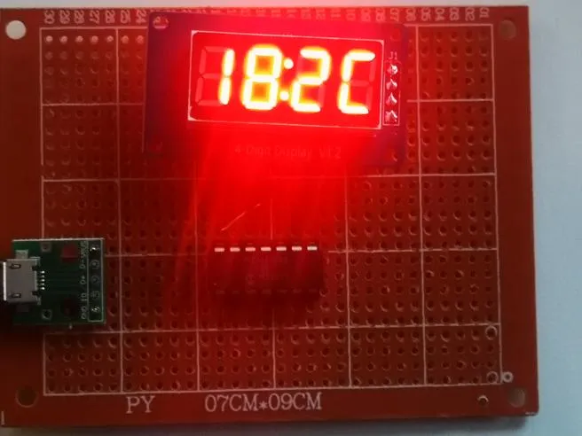
Final result
Finally I was happy with my build and was sure that it was giving me accurate results, and it turned out to be something actually useful, that’s a permanent exhibit in my room. The glowing red display is the bane of all camera sensors, however in real life it’s quite a beautiful and strong shade of red. Most importantly, it’s visible from all sides of my room and it measures the temperature, which means that all building requirements have been met. Most importantly, this project taught me the importance of planning and thinking about components, comparing them, and knowing when to change course. I could have wasted time with the SSD1306 displays, or have had an uninteresting “glue two Arduino libraries jankily and call it a finished product”, however I chose the path that would be both extremely educational and satisfactory and high-quality in the end. Finally, this is how the end product looks like. (In this photo the upper red dot is visible, however in real life it isn’t.)