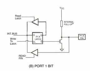
When you set a port as 1, you enable its pull-up resistor. It can’t source much current (“enough for 3 LSTTL loads”). When you read from a port, you’re not reading the value you set it as, rather you’re reading the voltage present at the pin. If you’ve set a port as 1 and something is pulling it low, you’ll see 0. However if you’ve set it to 0, then it’s straight to ground, so if something connected to that pin is outputting a 1, you’ll have a short circuit. This is why setting a pin as a 1 is effectively turning it into an input, and a pull-up, and an active high at the same time. It’s clever, it’s simple, and it’s called quasi-bidirectional!
Similarly to the serial, the register that you write to to output a value is different from the one you read to. This is evident from the diagram, as values you write directly set a latch, while the values you read are only the voltage present at each pin at the time you read it. This means that setting a port to all 1s and reading for 0s is effortless, though rather different from what you might be used to coming from PIC or AVR.
Sourcing much current is impossible from the chips themselves, however if you use a latch you can obtain high current sinking and sourcing. This also works well for protection and you can even use a bit of clever circuitry to obtain many more inputs or outputs using latches and shift registers which can source, sink and even tri-state.
One small issue that these kinds of ports have, which might be a dealbreaker in some projects, is the fact that if you set the port to 0, then the pull-up resistor is still there, sourcing current constantly. This consumes a small amount of power constantly, however in most cases this is beyond negligible.
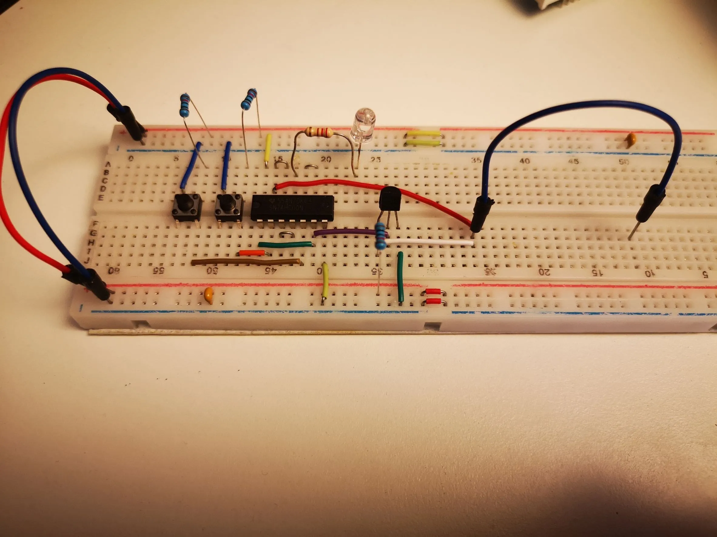
If you use the datasheet to calculate the current sourcing ability of the pins, you would get a result that gives you an approximate 50Kohm value for the internal pull-up resistor. So, to better understand the 8051’s quasi-bidirectional inner workings, I built the circuit from the hardware manual to show you how it works. I changed it a bit for clarity, but trust me, it’s the same one. Fight me on this.

The circuit is simple, it uses two pushbuttons that simulate the microcontroller writing as an output, and a buffer which simulates what you’d get if you read the input (red LED on means high, red LED off means low). You can also see that the part that contains the input and the output are completely separate “registers”.