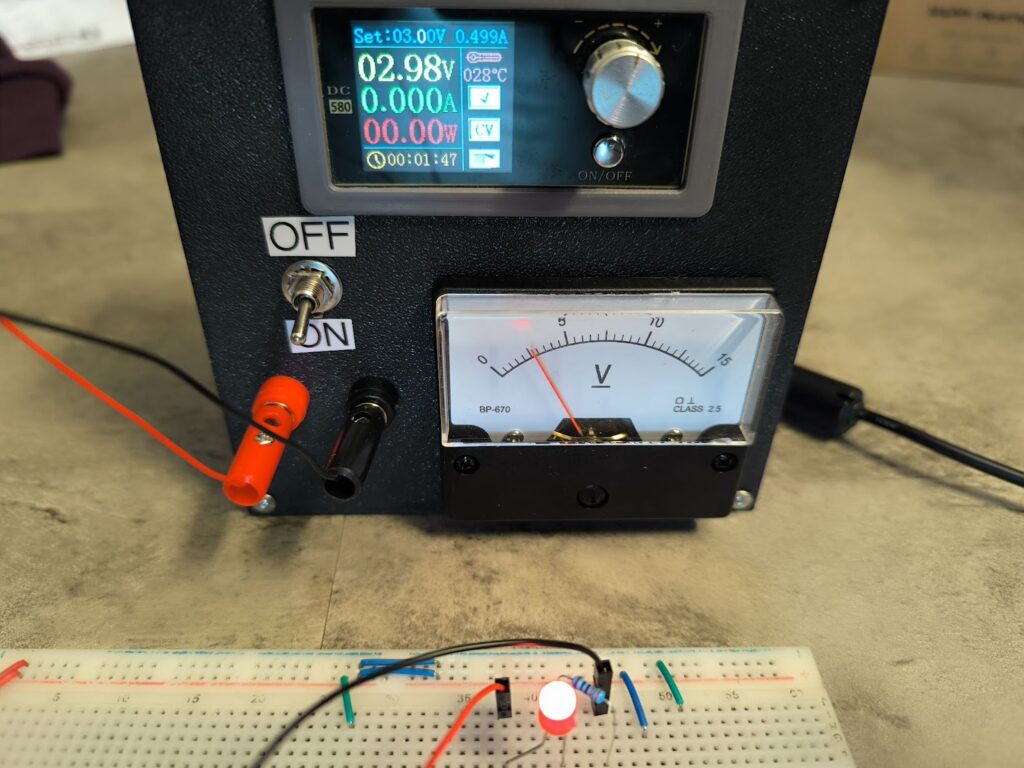
Four years ago, as I was starting to learn about electronics, I was a high school student with almost no money of my own in a country where Amazon doesn’t exist and import fees are about 50%. This required quite a lot of unorthodox solutions to obtaining parts and equipment. Mainly, this involved salvaging any kind of old electronics I could find, as well as buying things from Aliexpress. Naturally, both methods resulted in electronics that often didn’t work, but troubleshooting them was quite a valuable experience. Nevertheless, I always wanted to have a lab bench power supply. Before then, I had used a USB-to-breadboard adapter, which naturally limited all of my projects to 5V. One day in 2021, though, as I was scrolling Aliexpress, I found something I thought was ideal – a power supply module. Essentially, it was a digitally-controlled buck converter with a display and a knob that could be integrated into some kind of chassis. With a high-enough power supply voltage (e.g. from a laptop charger), you could use it as a regular lab-bench power supply that’ll cover most of the voltage and current requirements a regular project may need.
The module itself is quite compact, but also relatively heavy owing to the large capacitors and inductors as well as a well-sized heatsink with a fan. Nominally supporting up to 80W, it’s quite a beefy power supply. To work with it, I bought a laptop charger, because I very rarely use voltages above 19V (which most laptop chargers output), and the power output of a laptop charger is well-suited for the module, while laptop chargers themselves are very affordable. When I was at home in North Macedonia, I had a pretty janky setup with a generic plastic project box and the power supply system that generally worked. However, there were two main issues with this setup:
- The module was slightly too large to fit the box and I had no cutting tools to make that better.
- The module always output a voltage spike when the output was turned on, which crashed many digital logic circuits and likely damaged some too.
Now, as I got a new 3D printer (Bambu Lab A1) in Germany, I decided to finish this project once and for all. I took this as an opportunity to learn custom enclosure design and make the power supply I had wanted to make for four years. I laid out the following requirements:
- All wiring should be inside of the enclosure.
- All connections should have dedicated, proper connectors.
- Use an analog voltmeter dial to see the actual voltage output. Luckily, I had one that I bought for very cheap in Austria in Neuhold Elektronik, which is a wonderful electronics store.
- Turn a mechanical switch on/off to manually control the output, relying on the analog dial to see when the voltage stabilizes.
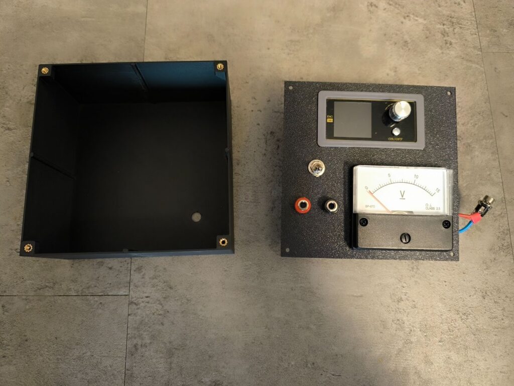
For the enclosure, I didn’t want anything special – just a simple front panel / back panel configuration. I really enjoy the look and feel of aerospace interfaces, so I wanted it to look like one. The design started with measuring all of the components and looking for any available mechanical drawings. I used free digital calipers I got from Aliexpress for this. I used Solidworks for the entire process, as I am already familiar with it through my classes. Solidworks is alright. I knew that I wanted the power supply module to be at the top center of the panel, and everything else below it. After exploring some different layouts in Solidworks, I settled for one that left the module at the top center, the analog dial at the bottom right, and the switch + connectors at the bottom left.
I then used a technique I do for all of my CAD drawings, which is to convert the 3D Solidworks part file into a Drawing. With a drawing, I can use my regular printer to print out the drawing on a piece of paper, lay out the parts (treating the paper as the final panel), and measure which manual dimensions I got right and which ones I didn’t. This saves me a lot of time and wasted filament, as it’s much faster to lay out the parts on a piece of paper and see which lines/holes overlap well. Usually, with this process, I catch ~90% of the alignment mistakes on the first try.
Even with my Bambu Lab A1, which is a staggeringly good printer, the tolerances aren’t perfect. Naturally, the laws of thermodynamics and heat expansion limit the possible dimensional accuracy, so I generally increase all small hole sizes by about 0.2mm (e.g. screw holes, circular connectors), and all large hole sizes (e.g. PSU module, analog voltmeter dial) by about 0.5mm from the value of the object I measure. So far, this method has resulted in consistently good fits. It’s not that much of an issue if the hole is too big, only if it’s too small.
After laying out the front panel, I designed the back of the enclosure using Solidworks’ assembly feature. Using the front panel as a reference, I designed the rear panel. Here, unfortunately, I made an oversight – I forgot that I should similarly treat the front panel as an external object and account for the expansion of the 3D printed plastic. During final assembly, this caused a small issue with the back panel slightly flexing, but it still fit decently well. For the back part of the enclosure, I just wanted a shallow box with a cutout in the front and small platforms for four screws to hold the panel in place. At the rear of the box, there would be a hole for the laptop power supply, and that’s it.
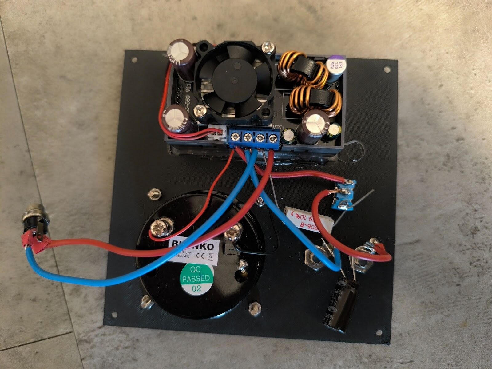
The assembly of the front panel taught me a few lessons about mechanical design. The power supply module had no screws – it relied on a clip. Though I planned around this, the clip connection didn’t feel very strong, so I hot-glued the module to the panel. Though not ideal, it made the connection very strong, which was particularly important since the front panel has a rotary encoder with a button to set the voltage and the current. To make sure the module stays attached after many presses, the hot glue helped a lot. The other parts, which were screwed on, went on surprisingly smoothly. My oversizing resulted in excellent fits everywhere.
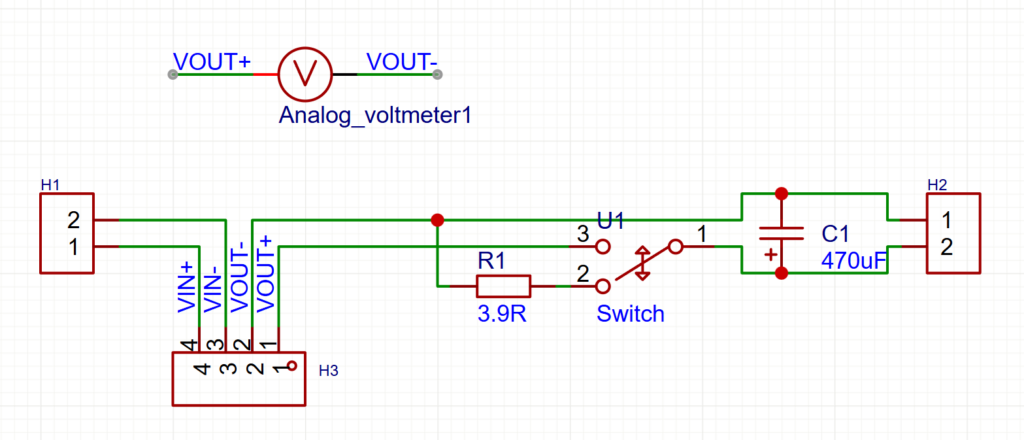
The back panel involved a bit of circuit design. I chose to have the voltmeter measure the voltage directly out of the module, so that I know what the actual voltage is before I turn on the switch. This will give it a few seconds to stabilize. Additionally, since I found the voltage output to be quite noisy, I added a 470uF capacitor, which smoothed things out quite a bit. To discharge the capacitor and make sure it doesn’t backfeed into the power supply when switched on, I added a large 3.9 ohm resistor. The resistor is wired such that it discharges the capacitor when the power switch is turned off. This additionally has the effect of discharging any similar capacitors on the connected breadboard/device, which reduces the potentially negative effects of a shutdown that doesn’t discharge capacitors (like brownouts).
The biggest issue I had during back panel assembly turned out to be the wiring of all of the connectors. Despite my experience in soldering, I still sometimes forget about tip oxidation. However, after getting a few extra tools, soldering has gotten much easier for me. Helping hands (from Lidl of all places…) make soldering anything with wires much easier in particular. For this project, I used two wire gauges – 18 AWG for the wiring that carries the current, and 26 AWG for the connection to the analog voltmeter.
Finally, after assembling it, I attached two labels with my label printer to show which side of the switch is on and off. I also put proper 4mm banana plugs to connect PSU leads. I bought a set of 10 banana plugs so that I can have one pair with female 2.54mm headers, one pair with male 2.54mm headers, one with Faston connectors, and the ability to make more. I made the custom lab cables myself with a wonderful Lidl crimping tool I got on sale. It’s very surprising how much decent electrical engineering equipment Lidl sells occasionally.
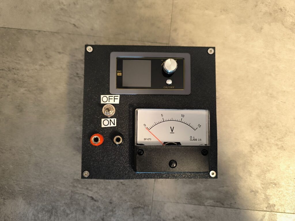
This is the final result. I really like how it looks, but more importantly, it’s a piece of usable, decent equipment that I was able to produce at home as a single person, which is truly incredible. While it does involve a lot of equipment, all of the equipment except for the 3D printer and soldering station is very cheap – and the cost of the 3D printer and soldering station is still 300 euros in total for something that will last and be regularly used for years.