I believe that the popularization of personal electronic calculators has been one of the biggest advances in education and technology of the 20th century. After the 1980s, practically anyone could calculate anything at the speed that they could type. For science, engineering, and education, this is a huge boon to people learning and working. While the US was the first to mass-produce personal electronic calculators in the 1970s, the USSR also realized the need to give people calculators – even more so, considering that their economy required immense resources for planning and that planning was initially done with vast numbers of “human calculators”, which were slow, unreliable, expensive, and demanded fair wages. That’s why the USSR had plenty of their own domestic calculators, all of which were interesting in one way or another. I had always wanted a Soviet calculator since every time I would research them, they would all have something peculiar about them. I already have multiple Texas Instruments TI-83 and TI-84 calculators, which I love and use extensively, but I just wanted a taste of what the other side of the Iron Curtain looked like.
Initially, I wanted to get one of the Elektronika MK-52 reverse Polish notation (RPM) programmable calculators, however, I saw many people having issues with them online. So I forgot about the whole thing for a while, as I focused on studying and working. A few months went by, and as I was selling an item on eBay, I saw a curious suggestion – a working Soviet calculator, with free shipping, for 20 euros. Even better – it was a desktop calculator with a plug and mechanical keys. This was interesting, this was unusual, and this was Soviet!
This one, like all MK-59s, was made in the Rodon factory in the city of Ivano-Frankivsk, Ukraine. There are examples of export versions and post-1991 versions that were produced, seemingly to ever-increasing quality, but like most post-Soviet businesses, they fell victim to the “shock capitalism” that traded all of the east’s resources, capital, and dignity, for blue jeans, Coca Cola, and scrubbing German toilets. The calculator was priced at 125 roubles, which is slightly more than half of an average wage at the time. However, given that this was a business-oriented calculator, the price seems quite normal. In contrast, simpler handheld scientific calculators were 30-50 roubles, which was only slightly higher than the American calculator/wage ratio, and comparable to the West German one. In this technology, as was in most cases, the Soviets were only ~7 years behind the West.
After waiting for 3 days for the calculator to come from lovely faraway Lithuania, it arrived in a quite used condition – made in May 1986 – almost 40 years ago. I immediately wanted to plug it in, since it was sold in a working condition, but I realized that the plug had a plastic shield around it (to protect fingers from frying) that didn’t fit in a standard EU plug. Some hardcore scissor snipping later, I got the death plug to fit, powered it on, and was immediately stunned by the gorgeous VFD display. Almost everything worked! Except for two buttons and two digits…
I subsequently decided to open the calculator up to see what was going on. Unfortunately, I was quite negatively disappointed. Age and use had withered away the circuit board’s traces, which were all beginning to rust. This is a common problem in these older circuit boards with exposed traces, and it’s a testament to the effort that went into designing them that many are still functioning. As I do with everything vintage I buy, I also immediately decided to replace the electrolytic capacitors in the power supply with high-quality Japanese capacitors. Since I didn’t have the exact values on hand, I generally went up in voltage and capacitance, to add some additional stabilization and protection. Surprisingly, when I measured the old capacitors, they were completely in spec and were closer to their rated capacitance than the replacements. Amazing!
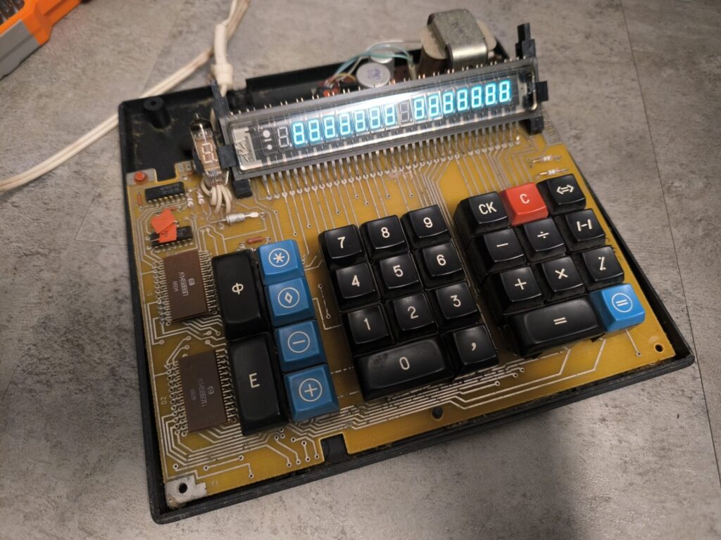
The design of the calculator is actually surprisingly elegant and clever. Most Soviet designs are similarly clever and are clearly made with a lot of thought. For example, all of the important signals of the calculator are routed to the edge of the PCB as an edge connector. This makes testing and debugging extremely convenient. The thermal design of the calculator is excellent, with most components staying at room temperature, thus contributing to a very high lifespan. The calculator has a minimal number of parts it needs to function. This results in fewer points of failure and, thus, a longer lifespan. The buttons are as simple as they can be, but also mounted in a clever way. The traces are thicker than they need to be, which ensures that even when starting to rust, there are still a lot of traces left over, while the voltages are always kept stable and with low series resistance. There are just many such clever design choices that make it feel more soulful than modern tech.
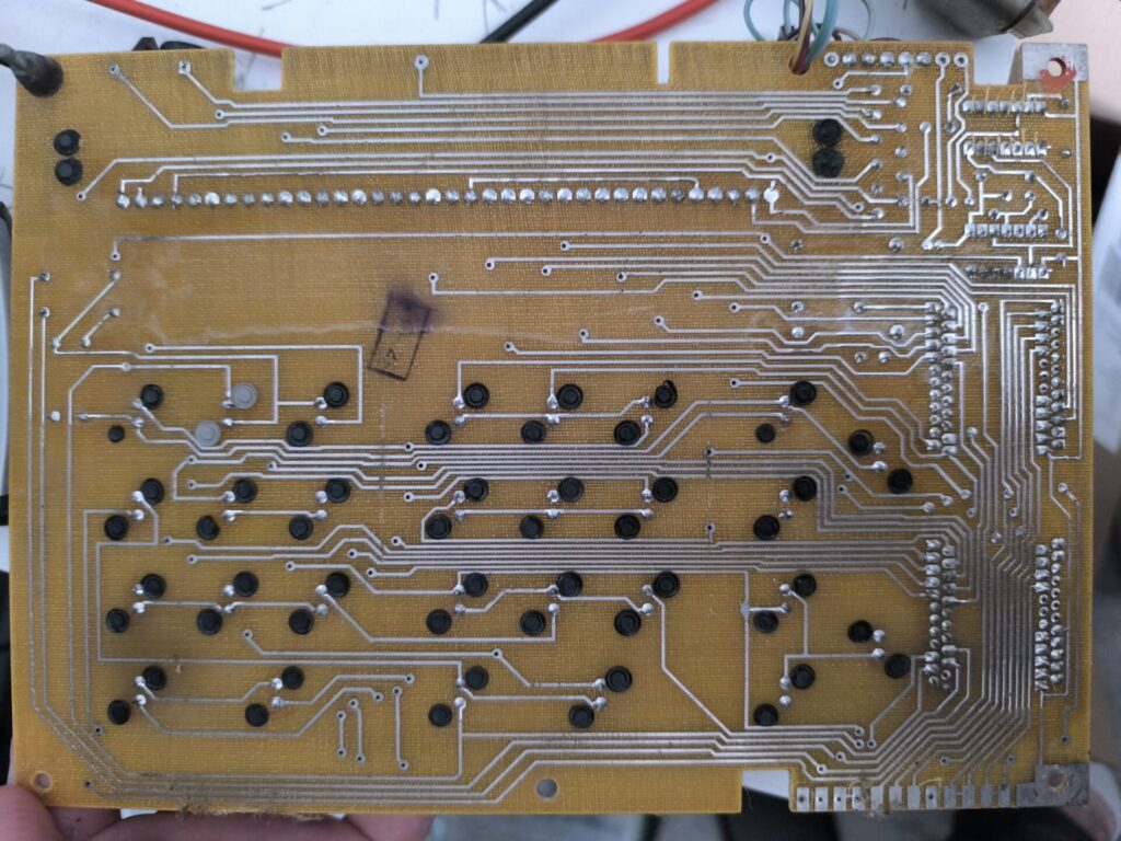
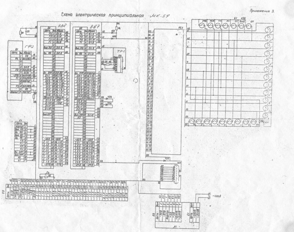
Unfortunately, the power supply schematic was not available online, or I’d have also replaced all of the other parts. The only schematic available online contains only part of the mainboard part of the circuit. The power supply seems to be some kind of linear regulator, but with a PNP transistor, so it probably regulates one of the negative voltages. I didn’t measure it because I don’t like poking around live circuits. Nevertheless, it works and all of the main board’s voltages are within half a volt of their rating. It looks quite normal.
However, the biggest issue was the two switches. The calculator was specifically marketed as having high-quality switches for the purpose of statistics and office work, and this one felt like it had seen a lot of office work. The key switching design was very clever and prominent in Eastern Bloc electronics. It was called a reed switch key, where the key would have a small magnet inside, and when you pressed the key down, the magnet would move over a reed switch – two bent metal rods inside of an inert glass ampule – and force them towards each other. The mechanism is extremely simple and the switches are made of just two plastic parts sliding over each other, a spring, a magnet, and a reed switch. The best part about them was that since there is no direct mechanical contact between the thing you push down and the thing that makes contact, the wear over time is drastically decreased, so the lifetimes are very high. Similar modern switches (Hall effect switches) can last billions of clicks and this is why the Soviet Central Commercial and Advertising Organisation highlighted the “reliable and accurate high-speed operations” of the MK-59.
None of this changed the fact that two switches weren’t switching. I tested them with a multimeter without power on, and indeed those two switches weren’t switching. From online research, I found out that reed switches need pretty good alignment to switch. Fixing them, unfortunately, is very difficult. I marked the switches as very worn and the PCB as quite infected. Next, testing the VFD digits manually, I found out that it’s likely that the output transistors of the extremely rare and specialized IC that drives the digits was broken. The digits would light up, but the calculator couldn’t. That’s another very difficult thing to fix.
Most normal people would give up. I, however, am not normal. This thing was too beautiful and just perfect for everything. Thus, I have decided that it’s time for a full redesign of the entire calculator, leaving only the original switches keycaps, VFD, and case. However, I’m not planning on doing a normal “put an Arduino in it and call it a day” conversion. This calculator was born with a Soviet heart, and it will be reborn with a Soviet heart.
I’m not sure if I’ve ever mentioned it, but for years I’ve been collecting sources and ideas for making a documentary about the Soviet electronics industry. Finishing that is one of my dreams, but it’s made almost impossible by the disgusting and evil Russian invasion of Ukraine. At the beginning of the war, through a mix of fear that Ukraine would fall and curiosity, I contacted one of Ukraine’s still-working integrated circuit factories – Kvazar, in Kyiv – to order a selection of the most advanced ICs they made during Soviet times. I ordered three Soviet versions of the Intel 8088, three more of the 8086, and a bunch of supporting peripheral ICs. The contact at the factory was incredibly kind and offered me all of them for a decent price, was patient with me while we figured out the best way to send money from one ruined country to another. The shipping from warring Ukraine to Macedonia took only a week, which is longer than shipping from one side of Macedonia to another, but I digress. They also sent me a book with short datasheets for all of the ICs I bought, from the early 1980s! All of the ICs I tested worked, but I just didn’t have time to build something with them.
I also got a ton of East German peripheral and logic ICs here in Germany. Again, due to a lack of time, I haven’t gotten around to using them. So I did some thinking… What if I just rebuilt the calculator out of Soviet/Eastern Bloc electronics? Calculators are relatively easy to code up, so I can focus on getting the design right. I’d just need to design a circuit for the Ukrainian 8088, which is a relatively nice microprocessor to design for (though, in my opinion, inferior to the Z80). So, here I officially announce the beginning of the design phase for the new Elektronika MK-59MK2!
As previously stated, I want to keep the aesthetic and feel as close to the original as possible. However, living in the 21st century means that I can also have some fun! I plan on adding the ability to communicate externally, through both WiFi and a serial port, for another long-term future project. In addition, I plan on redesigning the VFD circuit to run at a lower voltage and current to prolong its life.
The first thing I wanted to design was the keyboard circuit, because I’ve always wanted to build one. I wanted to go with Hall effect key switches, but I can’t find any that aren’t SMD mounted, so I’ll have to temporarily settle for Cherry MX pinouts while I get everything figured out.
Also, for future people looking at this who may want to repair their calculator, here are some tips:
- You really should replace the capacitors. The traces of the power supply PCB are thick, but they lift off easily. You can just merge them with the capacitor legs. Make sure to use a powerful soldering iron, because the PCB dissipates a lot of heat.
- You might also replace the PNP transistor. That one is just a generic medium-voltage (70V), medium-current (~3A), medium-frequency PNP, you can use a BD138 or comparable to replace it. You can get away with many other PNPs.
- If you can figure out what they are, definitely replace the Zener diodes and even the four square rectifier diodes. I’ve heard that the square diodes have a tendency to fail.
- Measure the resistors and look into replacing them. Even if they’re not broken, these have quite wide tolerances compared to modern resistors.
- Take care of the VFD above everything else. It’s by far the best part of the calculator.
- Theoretically, you can replace the power rails for the VFD with comparable adjustable DC power supplies, but ensure that you get something with a soft start, because most switching power supplies start out with a higher voltage and decrease it. This is really bad for VFDs. If all three of your power supplies are isolated, separate, and offer a DC rail, then you can get away with three positive power supplies for the two negative voltages and one positive voltage.