When you want to do something approximately, quickly, easily, and very reliably, you can always go with an analog circuit. Though they have gone out of fashion recently, analog circuits are ideal for when you make something that works at variable input voltages and/or currents. With a bit of analog magic, you can make the real magic happen.
This article will be long and divided into sections, starting with absolute basics (passive components), then active circuits with BJTs, then driving MOSFETs, and then op-amps, the final boss in analog circuits. It will also cover some other helpful basics like generating negative voltage rails and voltage rail management for analog circuits.
This article assumes some theoretical knowledge (~one introductory Electrical Engineering class) but zero practical knowledge. It was written for my university rocketry electronics club.
Passive component circuits
Voltage reference/divider
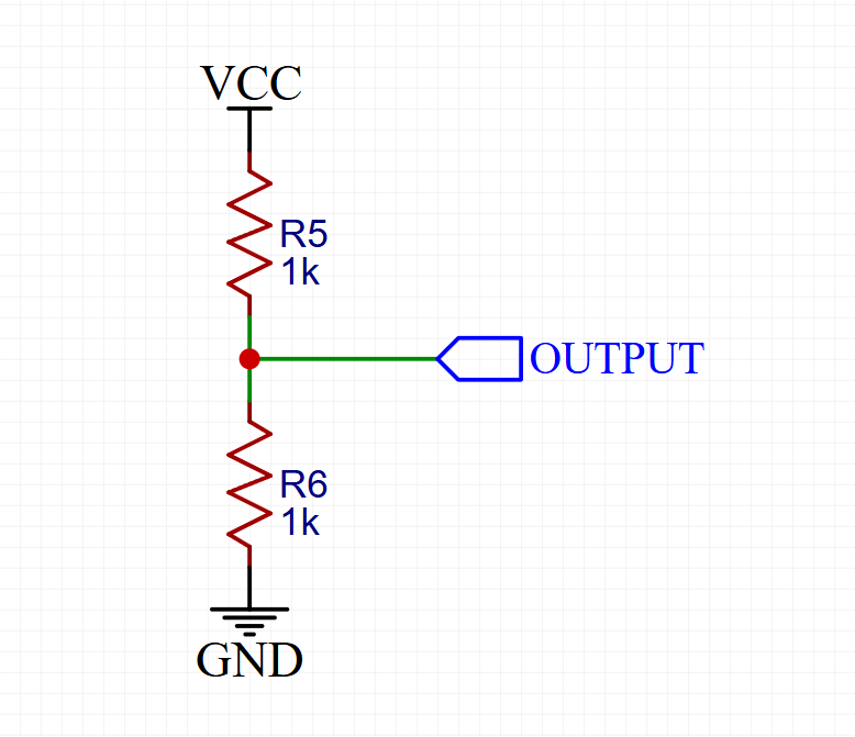
Let’s talk about one of those circuits that seems deceptively simple but hides quite a bit of complexity – the voltage divider. Although you could technically use a Zener diode or linear regulator to drop voltage, sometimes a simple resistive divider is precisely what you need.
Here’s why this works:
A voltage divider uses two resistors in series to create an output voltage that’s a fraction of the input voltage. The output voltage is determined by the ratio of the resistors: Vout = Vin (R2/(R1+R2)). Pretty straightforward, right? Well, not quite.
The clever part about voltage dividers is that they’re self-scaling – if your input voltage changes, your output voltage changes proportionally. This makes them perfect for things like:
- Battery voltage monitoring (though you’ll want some protection – see my article on IO protection)
- Biasing op-amps and comparators
- Creating reference voltages for ADC inputs
- Level shifting for sensor outputs
However, like many things in electronics, there’s always a tradeoff. Here’s what you need to consider:
- Loading effects – Any load connected to the output will form a parallel resistance with R2, changing your carefully calculated ratio. This is particularly nasty for ADC inputs where input impedance can vary with sampling rate.
- Power dissipation – Your divider is constantly burning power (P = Vin^2/(R1+R2)). This is bad but is made worse because increasing resistor values to reduce power consumption also makes your divider more susceptible to noise and loading effects.
- Temperature effects – Resistors have temperature coefficients. For precision applications, you’ll want matched resistors (ideally in the same package) to cancel out these effects.
- Noise susceptibility – High-value resistors make great antennas. In a noisy environment like a rocket, this can be particularly problematic.
For flying things, I personally recommend using voltage dividers primarily for low-speed monitoring tasks like battery voltage and supply rail monitoring. For precision measurements or high-speed signals, you’re better off with an active solution like an op-amp buffer or dedicated level shifter IC.
Current limiting
Let’s dive into current limiting – one of those fundamental concepts that shows up everywhere from LED drivers to protection circuits. We’ll start with resistors because they’re simple, then look at why capacitors and inductors can sometimes be better choices (spoiler: it’s all about where you want to waste your energy).
Resistive Current Limiting
The basic idea is pretty straightforward: Ohm’s law tells us that current through a resistor is proportional to voltage across it. Want to limit current? Add resistance. The math is simple: I = V/R.
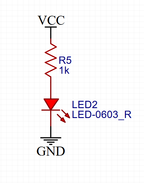
However, there’s a nasty catch: resistors dissipate power as heat (P = I^2 R). This is bad but is made worse because that power is being continuously wasted regardless of what your load is doing. Here’s where you might use them anyway:
- LED current limiting (for low-power indicators)
- Pull-up/down resistors (where current is very small)
- Protection for digital inputs
- Debug circuits where efficiency doesn’t matter
Capacitive Current Limiting
Now, capacitors are interesting because they limit current differently – they resist changes in voltage. The current through a capacitor is given by I = C dV/dt. This means:
- They naturally limit inrush current
- They don’t dissipate power like resistors (they store it instead)
- They only work for AC or transient conditions
You’ll see these used in:
- Power supply input filtering
- Motor start circuits
- ESD protection (where they shunt fast transients)
Inductive Current Limiting
Inductors are basically the opposite of capacitors – they resist changes in current. The voltage across an inductor is V = L dI/dt. This makes them particularly useful for:
- Switching power supplies (where they store energy temporarily)
- Motor drivers (where they smooth out current spikes)
- RF filters (where they block high-frequency noise)
The clever part about inductors is that they can limit current without dissipating much power – they store it in their magnetic field instead. However, like many things in electronics, there’s always a tradeoff:
- Inductors are typically larger and more expensive than resistors
- They can couple noise into nearby circuits
- They have their own parasitic resistance
- They can saturate if you push too much current through them
Personally, in power supply design, I prefer using inductors for current limiting where efficiency matters, capacitors for transient protection, and resistors only where simplicity trumps efficiency or where currents are very small. Combining these current limiting techniques, you can create filters, which are covered in the next topic.
Low-pass/high-pass filter
Let’s dive into filters – one of those fundamental building blocks that shows up everywhere from sensor interfaces to power supplies. Now, you might be asking yourself “why not just use a capacitor for everything?” Well, that’s where things get interesting.
Low Pass Filters
The basic idea is straightforward: a low pass filter attenuates high frequencies while letting low frequencies pass through. The math is simple: fc = 1/(2πRC) for passive filters. However, there’s a nasty catch that many designers miss – phase shift near the cutoff frequency can cause stability issues in feedback systems.
Here’s where you might use them:
- ADC anti-aliasing filters (personally, in flight computers I’ve often seen these before every ADC input)
- Power supply ripple reduction
- Sensor noise filtering
- Audio systems
A basic first-order passive low pass filter looks like this:
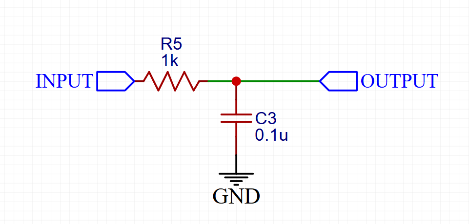
The clever part about low pass filters is that they’re self-compensating for noise – the higher the frequency, the more attenuation you get. This gives you -20dB/decade rolloff, which is cool but is made worse because you often need more. If you want more, you get into active filters, which I’ll talk about later.
High Pass Filters
High pass filters do exactly the opposite – they block DC and low frequencies while passing high frequencies. The cutoff frequency equation is the same, but the R and C positions are swapped:
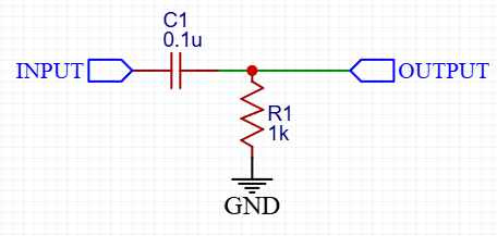
You’ll see these used in:
- AC coupling between stages
- DC offset removal
- Sensor baseline drift elimination
- EMI/RFI protection
Many ICs (specifically ADCs and analog front ends) now include active ways to measure and filter signals, but understanding passive filters is still critical for proper design. Like many things in electronics, there’s always a tradeoff:
- Higher order filters need more components
- Component tolerances affect cutoff frequency
- Temperature effects can shift your carefully chosen cutoff point
- Loading effects change filter response
For flight computers and precision measurement systems, I recommend carefully considering your frequency requirements before choosing filter values. A filter that’s too aggressive can destroy your signal just as easily as one that’s too “loose”. Online filter calculators, particularly sim.okawa-denshi.jp (Filter Design and Analysis), are excellent in this regard. There, you’ll also find many other filter types. You can just input your component values or desired features and get back both a circuit and its characteristics, with charts included.
The main requirement will be choosing your cutoff frequency based on:
- Signal bandwidth requirements
- Noise frequencies you want to reject
- Phase margin in feedback systems
The phase margin thing and assorted phase stuff are black magic for most people, so make sure to simulate things whenever possible in a tool that gives realistic results to the greatest extent.
Advanced passive filters
Let’s talk about some of those filter topologies that are slightly more complicated but can be extremely powerful. Twin-T and Pi filters are particularly interesting because they show up everywhere from power supplies to precision measurement circuits, yet many designers overlook their capabilities in favor of active designs, which may be more involved and require active components.
Twin-T Notch Filters
The basic idea is straightforward: a Twin-T filter uses two T-networks (hence the name) to create a very sharp notch at a specific frequency. Matching components is quite important here, as can be seen in the picture below. In effect, Twin-T filters are a combined low pass and high pass filter with a valley in the middle.
Here’s a basic Twin-T notch filter:
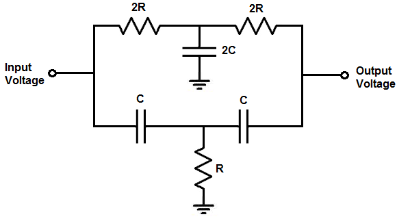
(photo from Notch Filter Calculator, which you should use to calculate your filter too!)
The awesome part about Twin-T filters is that they’re very precise in what they filter out – if you match the components well, you can get incredibly deep notches and leave all other frequencies relatively untouched. This makes them perfect for:
- Removing specific interference frequencies
- Power line (50/60Hz) rejection (VERY useful in the real world)
- Clock noise elimination
- Sensor signal conditioning
You can also build a relatively precise oscillator or specific-frequency amplifier with them, which you can learn more about in this article: Twin-T Oscillator Circuit with Op-amp
Pi Filters
Pi filters are an extremely useful class of filters in noisy contexts because they’re great at removing EMI and regulating ripple without wasting power. They’re called a pi filter because the capacitors and inductor kind of look like the letter pi. They’re generally used in power rails and you see them quite often in industrial environments or home computers because you can vary the type of inductor to achieve specific filtering. Specifically, if you put a power inductor as the main inductor, you can filter out switching frequencies and noise while also providing a voltage buffer. If you put a ferrite bead, you’ll filter out higher frequencies. If you’ve seen those plastic cylinders on long USB cables, those are ferrite beads (but you can also buy them much smaller for a PCB.
This is what a pi filter looks like:
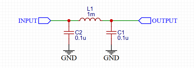
As stated above, pi filters are used for:
- Power rail noise filtering
- EMI reduction
- Low-frequency signal conditioning (usually in industrial environments)
Here’s a helpful related article: How to Use (and Not Use) a Ferrite Bead in Your Design to Reduce EMI
BJT circuits
BJTs are transistors that basically act as current amplifiers. Note that amplification doesn’t mean that they create current. They are like a faucet – they regulate the amount that can go through so that a little current (analogous to the force needed to open the faucet) can proportionally control a much larger current (analogous to the water flowing out).
In the modern world, you’ll rarely encounter BJTs used for pure current amplification. Rather, in most cases, you’ll see them used as switches, drivers, current limiters, or linear power supplies. The main ways they can be used practically are presented below.
LED driver
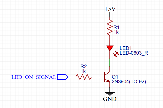
When you want a small, low-current signal to turn on something that takes moderate amounts of current (~5-500mA), this circuit is perfect. This circuit is most often used with outputs of microcontrollers or digital ICs, which don’t have the capability to directly drive an LED brightly. Note that even though the BJT could limit the current by itself, the variation of the current amplification ratio (the beta) between transistors makes this quite difficult to do precisely because small variations in beta cause huge shifts in current control.
Historically, the beta variation issue was so important that transistor manufacturers sold batches of “matched transistors” and even ICs that are just a bunch of identical matched transistors in a box. Nowadays, these ICs are still used in some places, and they can get quite expensive (example 340P14-U THAT | Mouser).
In addition, in most cases, you want to use an NPN transistor to control the current. This is because they’re usually cheaper and more convenient to control. An NPN transistor only needs a voltage at its base that’s 0.7V higher than the voltage at the emitter. Because the emitter is usually connected to ground, any positive voltage available will turn it on. However, for PNP transistors, you need a voltage that’s the same as the power rail voltage to turn it off. This means that unless both your power rail and control signal have the same voltage levels, it won’t work.
Learning to properly use any kind of BJT/MOSFET/opamp circuit requires practice and thought-out design, even something as seemingly simple as this. However, the good thing about these circuits is that they’re very easy to experiment with on a breadboard, so go experiment away!
Series regulator
One of the most used circuits in history is the humble series/linear regulator. Inside every linear regulator IC (e.g. 7805, LM317, AMS1117) you can find one of these:
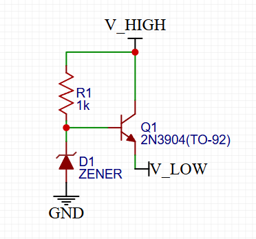
This circuit works as follows: R1 and D1 form a simple “voltage divider” and, by themselves, can be a low-current linear power supply. This voltage is then simply buffered by the NPN transistor. This means that the voltage will be “cut off” at the zener voltage and will never get higher, thereby regulating the current. Series/linear regulators are ideal for creating low-noise, simple power supplies that don’t require much current. A good rule of thumb is to keep their power dissipation at ~500mW (SMD) or ~1W (DIP). Otherwise, use a switching power supply.
Capacitance multiplier
An interesting variant of this circuit is a capacitance multiplier. If you replace the zener with a capacitor, instead of “multiplying” the zener’s voltage regulation, you “multiply” the capacitance – essentially filtering without the downsides of a massive inrush current and huge capacitor.
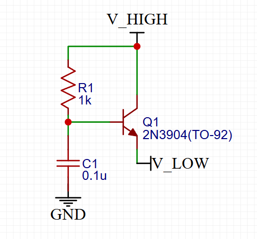
The effective capacitance is simply C1’s multiplied by the beta. The usual transistor beta is ~100, so you can get huge (effective) capacitances from small capacitors. An article with more information: Electrical Engineering – The capacitance multiplier revisited
Combining the two above circuits can make a very robust and low-noise linear voltage regulator.
Two-transistor current limiter
I won’t describe this circuit too much here because this article does it much better and in more detail than I can: Seemingly Simple Circuits, User-Proof External Supplies: Circuit 3: The Two-BJT Current-Limited Supply – Planet Analog
This circuit is also a variant of the series regulator.
Side note – this seems to be one of many awesome engineering websites/magazines that ended up being a casualty of internet enshittification – nowadays, it basically only reposts company marketing.
Inverting signal level translator
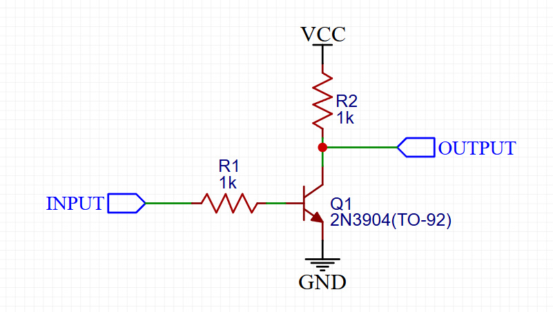
If you have a unidirectional digital signal with two different voltage ranges on each end, you can interface them easily with only a transistor. Note that this will invert the signal on the other end. By changing the resistor values, you can convert from relatively high to relatively low voltages and vice versa. Keep in mind that this circuit provides quite a bit of protection between the signal lines. However, you can make it even better by replacing the BJT with a MOSFET, which leads us to the next section.
MOSFET circuits
MOSFETs are one of, if not the most amazing inventions of the past century. Nowadays, they have gotten even better than anyone could imagine, with many relatively cheap MOSFETs having incredible specifications like multi-MHz switching speeds or <1mOhm resistance.
MOSFET circuits aren’t that much different than BJT circuits. However, the main difficulty with MOSFETs – given the immense possibilities afforded by their specifications – is actually driving them efficiently, quickly, and safely. A BJT, by definition, will have a current limit that will ensure that it destroys itself before it can do too much damage, but a MOSFET’s tiny resistance is almost as perfect of a short circuit as you can get.
There are many ways to use and drive MOSFETs, but this TI application note explains this orders of magnitude better and in more depth than I can: https://www.ti.com/lit/ml/slua618a/slua618a.pdf
If you read one document about MOSFETs in your life, this one should be it.
Opamp circuits
Similarly to the previous section, trying to explain opamps takes multiple books. However, they are so powerful that you can do literally everything the flight computer does with opamp circuits. There are two very practical books that explain 99% of all opamp circuits that you’ll see in the wild. They are:
- Analog circuits | TI.com (also available in PDF form)
- Op Amps for Everyone Design Guide (Rev. B)
Indeed, TI has over 700 pages of immensely detailed information about opamps, all available for free (but of course, you buy their opamps (which you should)).
Extras
Negative/higher-than-Vcc voltage rails
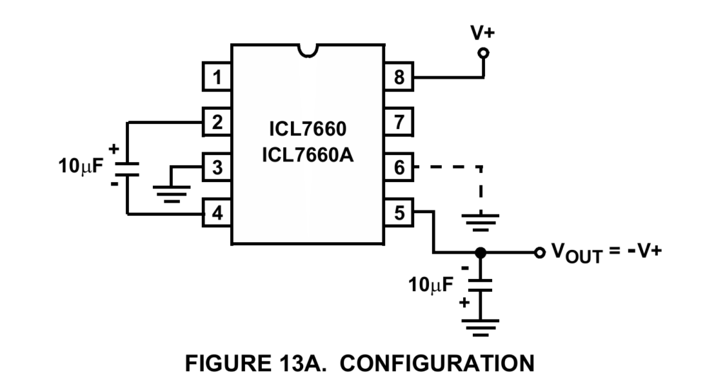
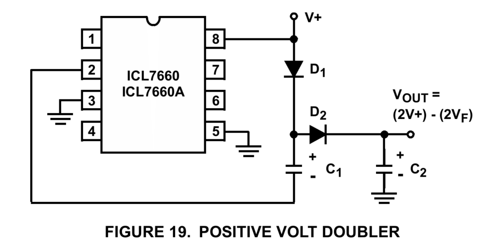
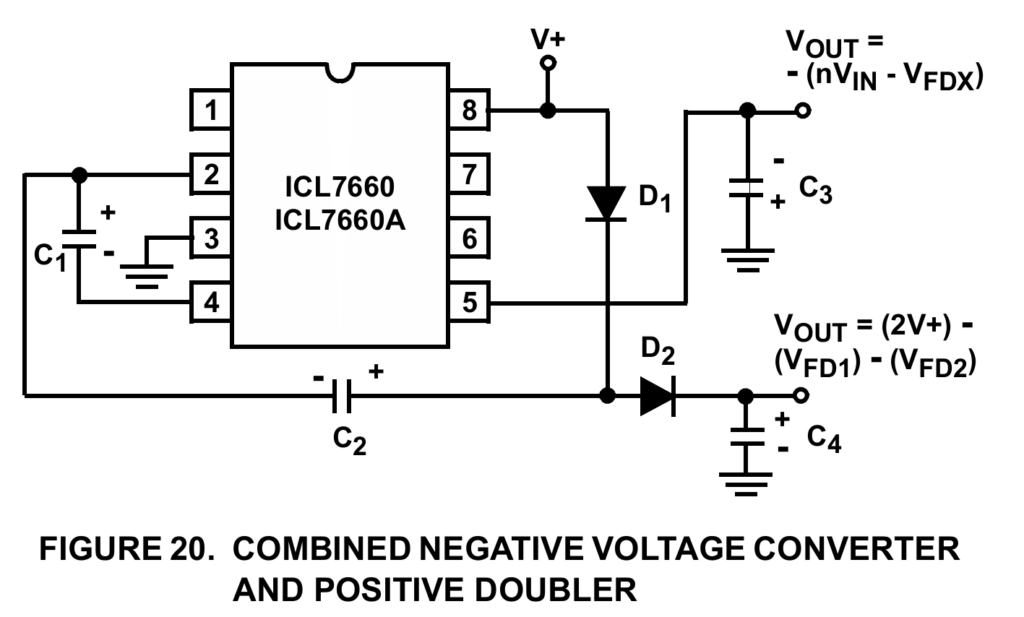
The easiest way to generate a low current negative voltage rail, or one that is above Vcc, is by using a charge pump. Using capacitors, charge pumps can generate a second voltage rail that you can use for opamp power supplies or driving MOSFETs with only one IC and two capacitors (plus two diodes if going for higher-than-Vcc). The most popular charge pump IC is the ICL7660, but you can find many others. Make sure that you’re drawing a maximum of one- or low two-digit number of milliamps from them, or their voltage will collapse quickly.
The basic negative circuit looks like this:
The positive circuit looks like this:
You can even combine them to get both variants:
Voltage rail generation (Vcc/2 method)
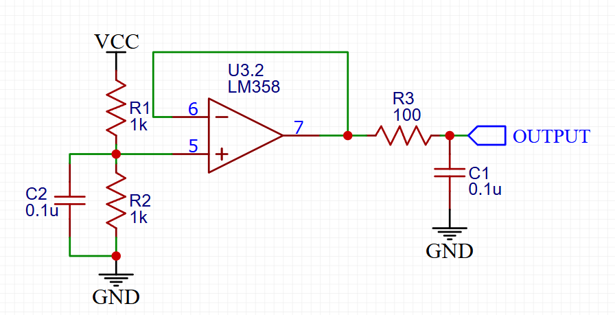
This is a buffered and filtered variant of the voltage divider circuit. It’s commonly used in guitar pedal circuits, but it’s useful in any kind of circuit where you need a very low-noise bias voltage, usually for signal conditioning and measurement.