1. Introduction
This is a series of three posts I wrote for my university’s WARR Rocketry club concerning IO protection for the rocket. They are copied verbatim.
2. Hardening
2.1. Backplane IO Hardening
Proper circuit IO protection requires circuits specially adapted to the function and potential risks the circuit will face. Although an advanced design, the rocket primary flight computer (PFC) faces the same risks as generic industrial devices, so it can use the same risk mitigation strategies.
In this context, high voltage will be defined as the voltage(s) used for the main resistive and inductive loads (12V or higher), while low voltage will be defined as the voltages used for logic and analog circuits (5V or lower). In the case of the PFC, a stray high-voltage output to a low-voltage IO pin is the primary risk and can be mitigated in a few ways depending on the normal operating conditions and limits of the circuit:
- Operating current – MCU pins operate with a very low current, so simple resistors can provide enough protection, while inductive/resistive loads require much more current, so they need separate risk mitigation strategies
- Signal speed – most simple protection circuits come at a cost of signal speed and current capability
- Proximity to other voltages and signals – high voltage signals right next to low voltage ones can be prone to accidental short circuits due to human error
- High side/low side switches – low-side switched loads have a high voltage on them at all times, and the connection of a high voltage to a low voltage connection is much more dangerous than connecting it to the ground voltage
2.2. Microcontroller protection
The microcontroller is responsible for most of the tasks out of all components, while also being at the highest risk of damage due to the size of its connector and the number of different connections. Combined with the low voltages at its pins and the high speeds of its signals, it presents a unique challenge to building protection circuits. For us, the most important parameters to protect the microcontroller’s pins are the current characteristics of the MCU found on page 94 (as of writing) of the STM32F429 datasheet.

The current sourced is relevant for shorts to ground, while the injected current is relevant for positive and negative voltages that exceed the -0.3V to 4.0V pin voltage limit. This current is to be dissipated by the input protection diodes of the microcontroller itself. Additional diodes from the pin to the supply voltage and from the ground to the pin can extend this maximum current, but the IVDD and IVSS limits must be respected, too.
For a maximum of 36V connected to a pin, a simple resistor to limit the current would need to be:
V=IR -> R= VI
R=36/5E-3=7200
The closest E12 resistor value is 8.2k, but 10k is a much more common value, which will have an even better effect. This simple resistor will be sufficient protection if the pin is low-speed and low-current. In particular, this will limit the output current to I=V/R=3.3/10000=330uA. For other pins with other conditions, however, other strategies are necessary.
2.3. Output pins
Regardless of speed, output pins can use a much simpler form of protection: a Schottky diode. For 3.3V outputs, a Schottky diode will only present a voltage drop of 0.3V, resulting in 3.0V. Since the CMOS standard requires at least 0.8*Vcc=2.64V to register as an active high, the 3.0V dropped by the Schottky diode meets this requirement (a regular silicon diode may or may not miss it). Ideal diodes would also work in this case. It’s important to note that Schottky diodes only retain their low forward voltage drops at around 1mA or lower of current, however most MCU pins fall below this limit. The main requirement will be a maximum reverse voltage of 36V (round to 40V) or higher. This Digikey filter shows potential diodes-in-a-box Diode Arrays | Rectifiers | Diodes | Electronic Components Distributor DigiKey.
The Schottky diode approach would still require a series resistor, however in this case a much lower resistance can be used which corresponds to the maximum output current of the MCU pins, since the only fault condition is a short to ground. In other words, since the output voltage is 3.0V and the maximum output current of an IO pin is 25mA, ignoring the small innate resistance of a Schottky diode, the needed resistance is R=VI=3.0/25E-3=120. Coincidentally, this is an E12 value!
For high-speed digital IO, a digital input protection IC will be necessary. Even though these ICs don’t have innate protection against a high voltage input, they can sacrifice themselves to protect the microcontroller and then be easily replaced while also providing ESD protection. Adding a pair of 3.3V TVS diodes to the other side would also protect the protection IC. The only issue with this approach is the added cost, however this approach could save the destruction of a much more expensive circuit board. This approach is mostly necessary for I2C, which is difficult to isolate with optocouplers or resistors, since I2C requires specific sequences of pull-ups which cannot be easily translated. An example of a digital isolator for I2C is TI’s ISO1540.
2.4. Input pins
Input pins are trickier, particularly if they’re analog pins. The resistor approach would work for many pins, while others could simply use an optocoupler. Digital or analog isolators, again, would also work.
Another issue arises with the inputs in the context of the rocket’s many high-current resistive and inductive loads, which can induce voltages due to EMI. This can be mitigated with a simple small capacitor; however, this would need to be adequately sized. The proper capacitance can be extremely difficult to calculate because of the effects of inter-trace capacitances, slew rates, and source impedances. Personally, in 5V industrial systems I’ve often seen 1-10nF capacitors in this role, however this requires special attention due to the higher speeds of some signals and the lower logic voltage levels of the whole system. This gets further complicated by the issue that the capacitors would be fully charged when the system power gets turned off and would discharge through the input protection diodes. A suitable series resistor would fix this issue. For 3.3V, this would be R=V/I=3.3/5E-3=660 ~ 680.
This would require further research and experimentation but could drastically increase protection against any possible induced voltage spikes. In terms of the effect on the speed of the signal, this circuit can be represented as a two-stage passive RC low pass filter where the second capacitor is formed by the MCU’s IO pin capacitance (5pF for the STM32F429 according to the datasheet) combined with an approximate PCB trace capacitance (7pF according to the STM32F429 datasheet estimations). According to the famous Okawa Denshi (2nd order CR Low-pass Filter Design Tool – Result – (okawa-denshi.jp)) calculator, this results in a center frequency of 557kHz.
2.5. Simple 36V input and output protection
When a signal is low-speed (approximately <10kHz), simple resistors and diodes can do the job well. A standard circuit for protecting inputs (as of writing) looks like this:

Simulating this circuit in Falstad with a 36V input and a 3.9V Zener diode results in a ~500mW power dissipation at the first resistor, a ~100mW power dissipation over the Zener and a ~3.5mA current injected in the microcontroller pins, which is within their safety specification. Unlike a simple 10k resistor, this circuit does not increase the series resistance by as much (approximately a third), while also providing the additional benefit of the Zener’s other diode to protect against negative voltages. The 3.9V value is a good tradeoff, given that 3.3V signals can have relatively wide tolerances of +-5%, while Zener diodes usually have a tolerance of +-0.2V. In this case, the second resistor will protect against slight overvoltages, while the Zener and the first resistor will protect against large overvoltages. This circuit can also use a 1k resistor instead of the 2.2k, but the power dissipation would have to be doubled to 1W.
3. Final backplane protection
3.1. IO protection
The IO protection circuitry grew to be quite a bit more complicated than I expected when considering all the possible situations that the IO would need to be protected against. The protection is divided into two parts – IO and power rail. Initially, I had wanted to use simple resistors and diodes to protect the circuitry, however, the requirements made this impossible:
- Low series resistance due to I2C and SPI passing through. I2C would require around 100 ohms of series resistance to work properly, and likely even lower due to the length of the traces and the wires connecting it to the external world.
- Bidirectional input and output, which negates the use of diodes.
- Low input capacitance is due to the long traces and the presence of high-speed signals.
- Fast response time due to the IO being directly connected to the MCU, which is very vulnerable to even short overvoltage conditions. This negated the use of fuses.
Thus, with diodes, resistors, capacitors, and fuses out of the question, it was obvious that some active circuit protection would be needed. The requirements for this were also quite stringent:
- I2C necessitates very low quiescent current due to its pull-up resistors, thus a quiescent current at the operating voltage of I2C (3.3V) would have to be practically zero.
- The circuit must be self-powered because external power might not be present during overvoltage.
- The circuit would need to be compact due to the many external IOs.
- The circuit should have some indication that an overvoltage condition is occurring.
- Due to an overvoltage condition, the circuit should not damage any components (either in itself or externally).
The main goal was to include overvoltage protection, however with the chosen protection circuit there is a natural overcurrent protection as well. This will be explained further. Another quick note here is that the threshold for protection is somewhat flexible, due to most of the IOs of the STM32 microcontroller used being 5V tolerant. As a result, a lot of the circuitry can be simplified.
I started by googling different protection circuits, however I found none that fit the requirements except for one made by Maxim Integrated which showed a really clever circuit that I’d never seen before – AN5026.pdf (maximintegrated.com).
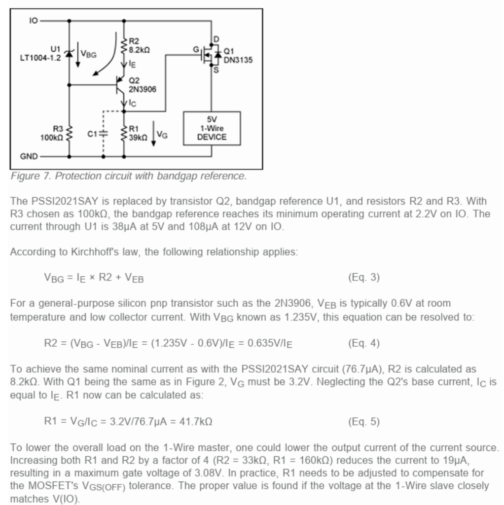
This circuit was excellent and very well documented, including oscilloscope pictures that show the excellent response times and low quiescent current of the circuit. The most interesting part about it is the use of depletion-mode MOSFETs, which are rarely used outside of power applications, but are generally really cool devices. The depletion-mode is normally-on and will turn off if the voltage at its gate is ~3V lower than the voltage at its source. To make my desired changes, I brainstormed for a while until I designed another similar, yet also interesting circuit.
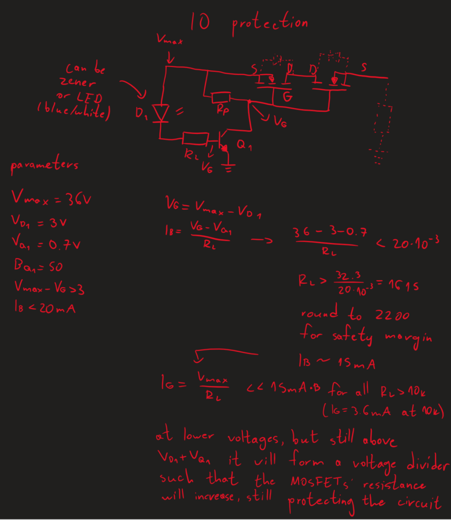
This circuit uses two depletion-mode MOSFETs back-to-back with their gates and drains connected. This ensures bidirectional protection. The pull-up resistor at the gates ensures that the voltage at the source is identical to the voltage at the gate, which will keep the MOSFETs turned on. However, once the voltage threshold set by the diode and the NPN transistor’s inherent diode-y thing is reached, the NPN will pull the voltage down to ground, making the voltage at the gate more negative than the voltage at the source, effectively turning off the MOSFETs. Due to the high pull-up resistance (~50-100k would work nice), it takes very little current to quickly turn the MOSFETs off faster than my somewhat slow USB oscilloscope can measure.
At an overvoltage condition, this circuit will work exactly like a voltage regulator and clamp the voltage at a set level. You can see this from my oscilloscope measurements (the yellow voltage is the input, the blue voltage is the output, look in the middle of the bottom of the black area):
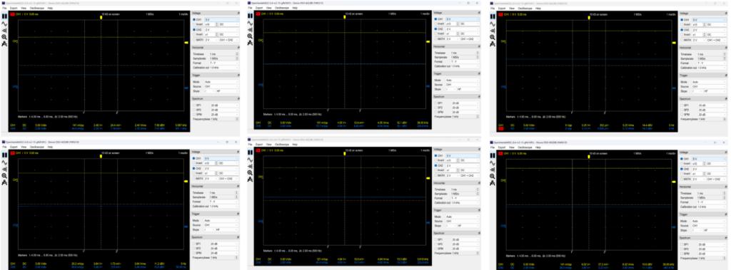
During my testing I set the overvoltage protection at 5.6V, which when reached limits the MOSFET’s voltage to its Vgs, which is usually ~3V. In this way, the circuit acts exactly like a voltage regulator, and automatically solves all overvoltage conditions. I was able to go up to 30V (which my oscilloscope can’t measure, but look at the last picture for 24V) without the MOSFETs even warming up a little.
Because the MOSFETs are normally-on, the monitoring part of the circuit with the diode needs to only be connected to one source. In this case, the diode is an LED, which has the additional benefit of indicating when an overvoltage condition is happening, for visual debugging. Generally, this is a pretty cool circuit and works really well.
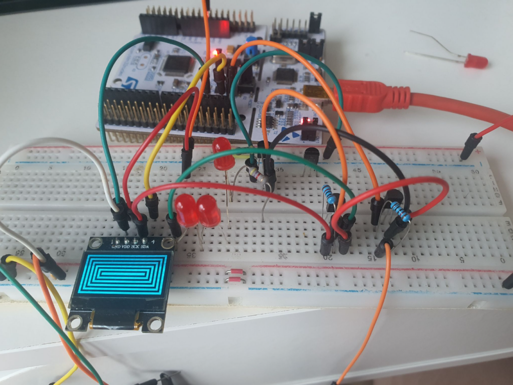
Testing with an I2C display also shows that the circuit can let I2C pass through, which was one of the most difficult goals. Both SCL and SDA were tested and worked, even with a 10k pull-up resistor.
For more precise control, the LEDs can be replaced with zener diodes, however you would lose the visual indication. For the final circuit, I chose 3V blue LEDs, which when combined with the NPN’s 0.7V drop, results in a 3.7-4V threshold, which is pretty nice and works well with the 5V-tolerant STM32.
3.2. Power rail protection
The power rail protection had three main requirements
- Overvoltage protection
- Overcurrent protection
- Reverse polarity protection
While undervoltage protection and inrush current limiting would be nice additions. Even though discrete circuits that can fulfil all of these requirements existed, I wanted to use something more professional and without many moving parts. Generally, since the IOs were well-protected for voltages up to 30V (and more, with a different MOSFET choice), I wanted something that could also withstand the full potential 36V connected to the power rail. After looking at TI’s portfolio, I came across an incredibly powerful power-rail protection IC that had basically everything you could ask for – TPS2663 data sheet, product information and support | TI.com. It was well-documented, with a large and detailed datasheet, a relatively low price and a small, but hand-solderable SOP footprint. Built for industrial power rail protection, it could do basically everything, and in addition to that it also had a downloadable spreadsheet where you can input your requirements and it will choose the parts for you. After reading parts of the datasheet and doing some thinking I came up with a nice circuit with E24 resistor values that uses only the parts of the IC that I needed. This circuit included overvoltage protection, undervoltage protection, reverse polarity protection, inrush current limiting, overcurrent protection, and all that while only adding ~50mOhm series resistance.
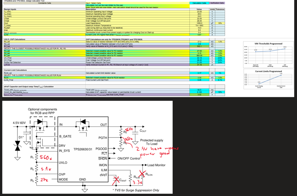
The circuit above is the 24V variant, while the circuit below is the 5V variant.
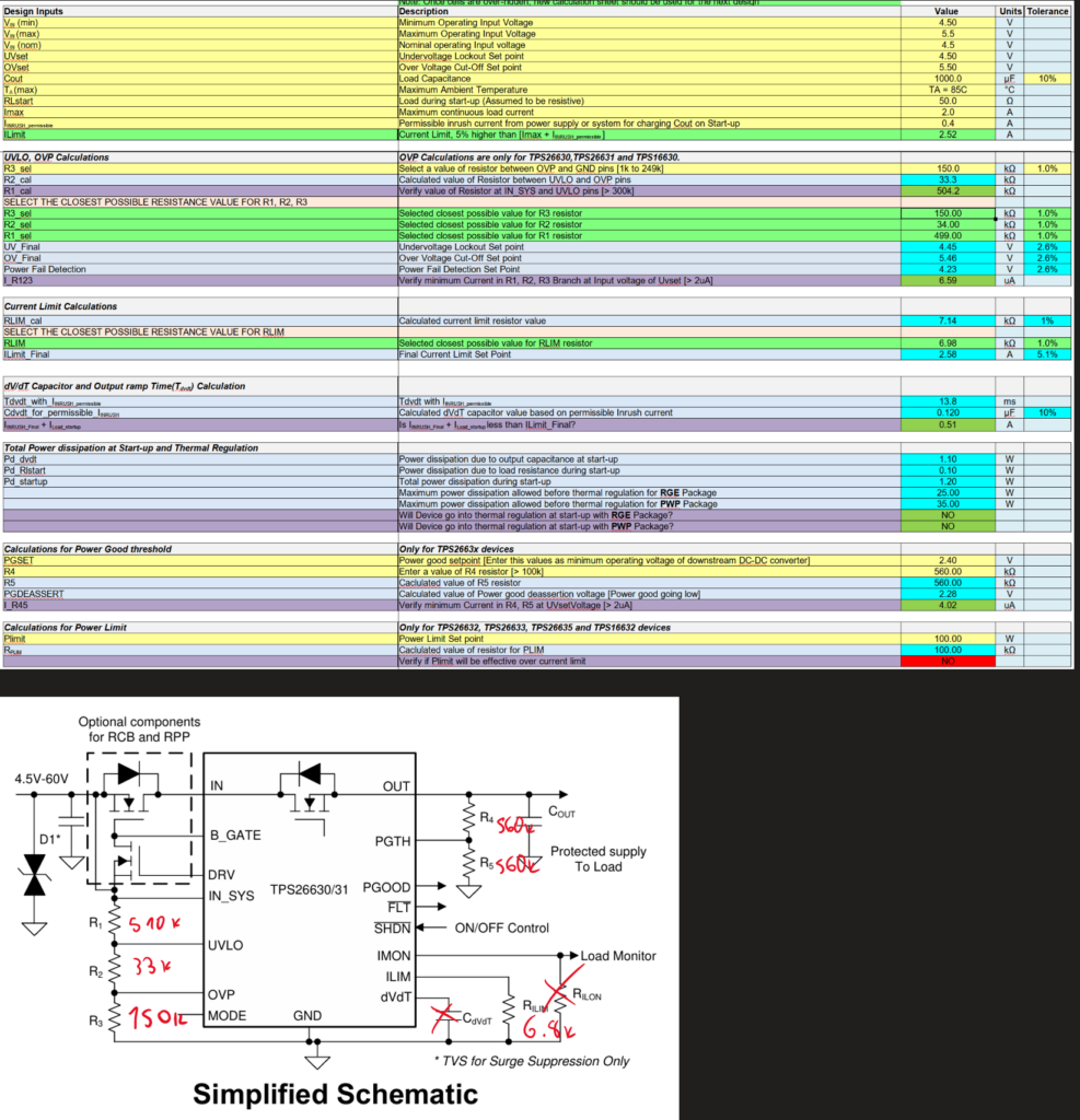
There’s not much more to say about this circuit. Thank you, TI, for being so nice to customers. For reverse polarity protection, the MOSFET at the top needs to be a low-Rdson N-channel MOSFET (you can reuse one already present in the design, just make sure it can handle above 36V), while the bottom one can be any small-signal N-channel MOSFET (like a BS170).
4. Common issues with RS485 and solving them on the flight computer
4.1. Basic information/refresher on RS485
RS485 is a long-distance medium-speed communications protocol that usually only uses two wires in a differential pair to connect two or more devices at a distance of up to a few hundred meters, at a data speed of around 10Mbps, depending on the transceivers’ moods. RS485 is cool because the whole bus can only be connected with two wires while staying relatively simple and resistant to EMI and nasty factory stuff. The two wires carry signals called A and B, for which only the voltage difference matters. If A is sufficiently higher than B, that’s a 0; if B is sufficiently higher than B, that’s a 1. The good part about them being differential is that when an external voltage is induced on the wires, the same voltage will be induced on both. However, since only the difference matters, you’ll basically get (for example): (A + 5V) – (B + 5V) = A + B. Thus, noise immunity! There are other things like bus termination and transmission line stuff, but that’s only relevant at longer distances. Generally, though, at the start and end of your RS485 bus, you should put a ~120 ohm resistor between A and B.
Also, the maximum and minimum voltages for an RS485 line are 12V and -7V, respectively.
You can read this document for more basic information, but here, I will only cover the parts that are relevant to a student flight computer that communicates with ground control. You can read this great TI application note to learn more: https://www.ti.com/lit/an/snla049b/snla049b.pdf
4.2. Failsafe biasing
For older RS485 transceivers, if nothing was driving the bus, the state of the bus was unknown. This is particularly nasty for RS485 since the voltage levels look like this:

You’ll see that between +200mV and -200mV, there is nothing, and this means that this is an invalid state with undefined behavior. This is bad but is made worse because RS485 termination adds a relatively low resistance (~120 ohms) between A and B, which means that having nothing driving the bus will practically always result in an unknown state. However, the current RS485 driver in the flight computer (ICL3173) has integrated bias resistors, which bias the lines to a difference larger than 200mV in either direction. From the TI document above, an example failsafe biasing circuit is:

However, note that modern ICs integrate this in some form, and this circuit is not really recommended anymore because it messes with other RS485 voltage and current characteristics. Many ICs now include active ways to measure no drivers and act accordingly.
4.3. Overvoltage protection
Protecting communications lines from overvoltage while retaining all the other necessary characteristics is one of the hardest parts of building robust industrial-adjacent circuits. Much like the IO protection with the depletion mode MOSFETs, creative thinking and component choices are needed to make this work. Now, you might be asking – couldn’t depletion mode MOSFETs work here too? Well, not really. First, RS485 is differential, so there isn’t a defined direction in which overvoltages can go – they can either be negative or positive. The depletion mode MOSFET circuit could only regulate positive voltages. While I think it could be modified to work with both, the complexity would increase greatly, and the circuit would require testing. This would take time and effort, which seems unnecessary when there is probably a better solution… right?
In this case, one important thing that makes life easier is that IO protection requires directly protecting sensitive microcontroller pins. However, RS485 transceivers are better protected and can survive nastier events, including in the negative voltage range (since that’s half of their job).
As always, TI comes to the rescue with an application note – https://www.ti.com/lit/ug/tiduer9/tiduer9.pdf (well, not always; the MOSFET circuit was mostly mine, and TI did not make it). In this case, they propose another wacky component: a SIDAC. The name is an acronym for Silicon Diode Alternating Current, which doesn’t say anything about what it does, but its operation is really simple. The SIDAC doesn’t conduct until the voltage difference between its two pins reaches a specific value called the breakover voltage: Vbo. Once it reaches Vbo, however, it becomes a bidirectional diode (basically a short circuit). It stays a bidirectional diode until the current passing through it falls below a certain threshold (called the holding current). So, it is voltage-activated and current-deactivated. Now, this sounds convenient, but if we short-circuit the input voltage to a reference point, we’ll just burn the SIDAC and the RS485. We could control a relay to completely disconnect the input lines or add a fuse that will engage after the SIDAC. However, the first option is more complicated (because it requires a driver circuit) and takes a lot of board space. The second option is too slow because even fast fuses take at least a few hundred milliseconds to activate. The solution is a resettable fuse in the form of a PTC, which is the perfect component to go along with the SIDAC for this circuit. PTCs, if you don’t know, are just resistors whose resistance increases as their temperature increases (that’s why the name stands for positive temperature coefficient [resistor]). This makes them very convenient for circuits where you want to limit the current going through a resistor by using the simple fact that resistors heat up when current flows through them. By selecting a specific PTC, you can get a pretty fast fuse that will regulate current by itself up to a specific maximum.
This sounds like a perfect match for SIDACs for an overvoltage protection circuit because the following will happen when an overvoltage condition is reached:
- SIDAC reaches Vbo
- SIDAC short circuits the input to ground
- Current drastically increases
- PTC heats up because current increases
- PTC’s resistance increases
- PTC’s current decreases because resistance increased
- Current falls below SIDAC’s holding current, so SIDAC turns off
Now, the only issue becomes component choice to get this specific response quickly enough while not triggering for regular RS485 voltages but triggering for anything higher. This is actually quite complicated since PTCs are real-world components with many tolerances and parameters. Important PTC parameters are:
- Holding current (completely different from SIDAC’s holding current) is the maximum current the PTC can sustain without heating itself up to a high resistance.
- Trip current is the minimum current required to heat the PTC up to a high resistance. Note that there is a gap between the holding current and the trip current which is due to tolerances and ambient cooling/heating.
- Trip time is the maximum time that a PTC at the trip current takes to reach a high resistance.
- Initial resistance is self-explanatory, and trip resistance is the resistance measured about an hour after a trip. These types of fuses take a while to stabilize.
Based on the RS485 specifications, the maximum sustained current for an entire RS485 bus is 60mA, but that’s with all 32 RS485 devices on the bus. This will be the upper limit for the holding current. Anything higher than that is an overvoltage/overcurrent event. Thus, the trip current should be similarly low. The trip time should also be as low as possible. TI’s choice in the application note is fine, but TI expects much higher voltages to be present and specifies the PTC accordingly. The biggest threats on the flight computer’s RS485 inputs are 24-36V accidental connections, so a lower trip time and lower trip current are necessary. Some messing around with Mouser’s parametric search (PCB Mount SMD/SMT Resettable Fuses – PPTC – Mouser Germany) results in many parts, most of which would work.
Let’s take this part as an example: https://www.mouser.de/ProductDetail/Bourns/MF-NSMF005-60X-2?qs=Z%252BL2brAPG1Ih8mF6OSnkGQ%3D%3D
It has a regular maximum resistance of 20 ohms. For a 24V short circuit, this means that the current will be 1.2A. Trip time drastically decreases as the current increases. From what I’ve seen in datasheets, the trip time decreases by a factor of ~10 for a current double the trip current. We can also just look at colorful graphs like real engineers. For >1A, we already have a trip current of less than 10ms.

Also, this PTC looks pretty, so it’s the best choice. Now that we have a PTC, it’s time to choose the SIDAC. Interestingly, even when doing a parametric search for SIDACs, given the conditions needed for RS485 protection, the same SIDAC that TI chose appears. That’ll be the one.
15 V Thyristor Surge Protection Devices – TSPD – Mouser Germany (parametric search)
https://www.mouser.de/ProductDetail/Bourns/TISP4015L1BJR-S?qs=icxiLNvuT4q%2FjXYlmg%252Bp%252Bw%3D%3D (part choice)

Here is what the circuit would look like (this is directly from the application note).
4.4. Closing thoughts
Modifications of this circuit would work on many other circuits as well. The family of components that the SIDAC belongs to – thyristors – can be extremely powerful, but they are difficult to learn and master. If you liked this post, please visit my blog (snikolaj.com) and send me an email. I love receiving emails.