Introduction (do you guys really need it?)
The USB-UART converter is the Swiss army knife of the post-Arduino hobby electronics world. UART has been a default communications protocol for many things since the 80s, however with the decline of all ports except for USB, especially the parallel port, computers haven’t been able to communicate much with external electronics. Since the proliferation of ARM microcontrollers with built-in USB bootloaders is only a recent occurrence, most computer-to-external-world communication has occurred through USB-UART converters. The most famous of these was the FT232RL, however after FTDI’s public relations disaster, most hobby-focused electronics have tended towards the WCH CH340G, SiLabs CP2102 or WCH CH9102.
Recently I found myself in need of a 3.3v 115200-baud UART for a pair of Sipeed Lichee Nano tiny Linux Single-Board Computers (SBCs). Their main external communication happens through UART and that was the only way to communicate with them. Initially I tried to use my (likely clone) FT232RL adapter, however it suddenly died. It didn’t want to enumerate on my Windows PC and became uncomfortably hot with nothing connected, meaning that something likely short-circuited inside. I remembered that all Arduino and Arduino-compatible boards have a USB-UART converter, and if the Arduino is set in a perpetual reset state by grounding the RST pin, the UART can be used independently. However, at 3.3V, only using my ESP32 was feasible if I didn’t want to damage the boards.
This worked perfectly, however, I still needed to use my ESP32 for other projects, so I had to find a replacement, and since I needed one quickly, I had to improvise with what I had at home. My immediate thought went to cannibalizing a broken ESP8266 for its CH340, which appeared to be a good idea until I discovered that the CH340 didn’t work either. Maybe it was the issue all along…
Regardless, I had to find a solution, so I tried to simply use Arduino SoftwareSerial to make a software USB-UART converter. The original SoftwareSerial for the Arduino Uno works at a max speed of ~38000 baud, so I tried using an STM32, which is significantly faster, however it missed bytes all the time at 115200 baud, which means that it’s likely some code inefficiency in the SoftwareSerial library that imposes the limit.
Design goals (I wish my relationship goals were as simple as my design goals)
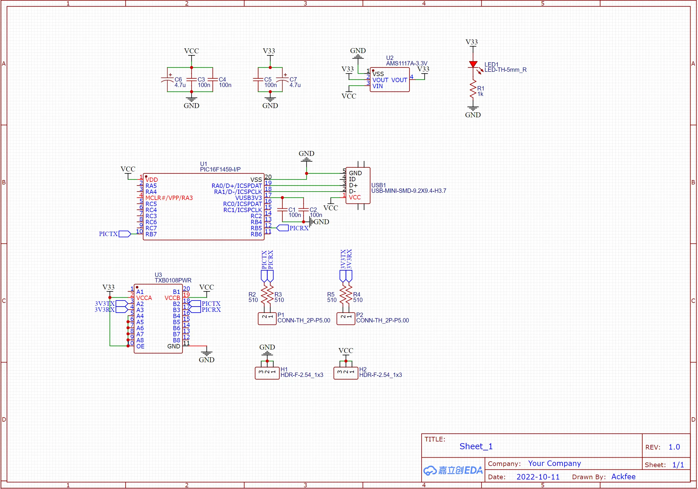
My mind then went to using a PIC microcontroller with USB to do the job. I have two types of PIC microcontrollers with USB, a PIC16F1459 and a PIC18F4550. For the job I chose the former since it’s DIP-20 as opposed to DIP-40 and it had MLA support. For those who don’t know, Microchip’s MLA is a tool that generates custom libraries for Microchip microcontroller peripherals. The MLA support of the PIC16F1459 meant that would need to write practically no peripheral code, however the nature of the tool made me a bit suspicious, which I’ll discuss later. However, first I wanted to take care of the hardware.
The main design goal of the DIY USB-UART converter would be to get reliable 115200-baud transmission at both 5V and 3.3V without making any compromises, while adding some protection to the inputs, which many Arduino-like boards neglect. The idea I came up with was to use the PIC16F1459 at the USB voltage, 5V, and then use a level shifter board based on the TI TXB0108 to level shift the signals. The TXB0108 is great because it automatically detects the direction of the signal and level shifts accordingly, meaning that no complicated circuitry needs to be used, while the signal drive is still quite high. Still, using only RX and TX with the TXB0108 is a bit of a waste since it has eight level shifting ports, but I don’t have the two-signal variety. The board also had filtering capacitors added, which was a nice touch.
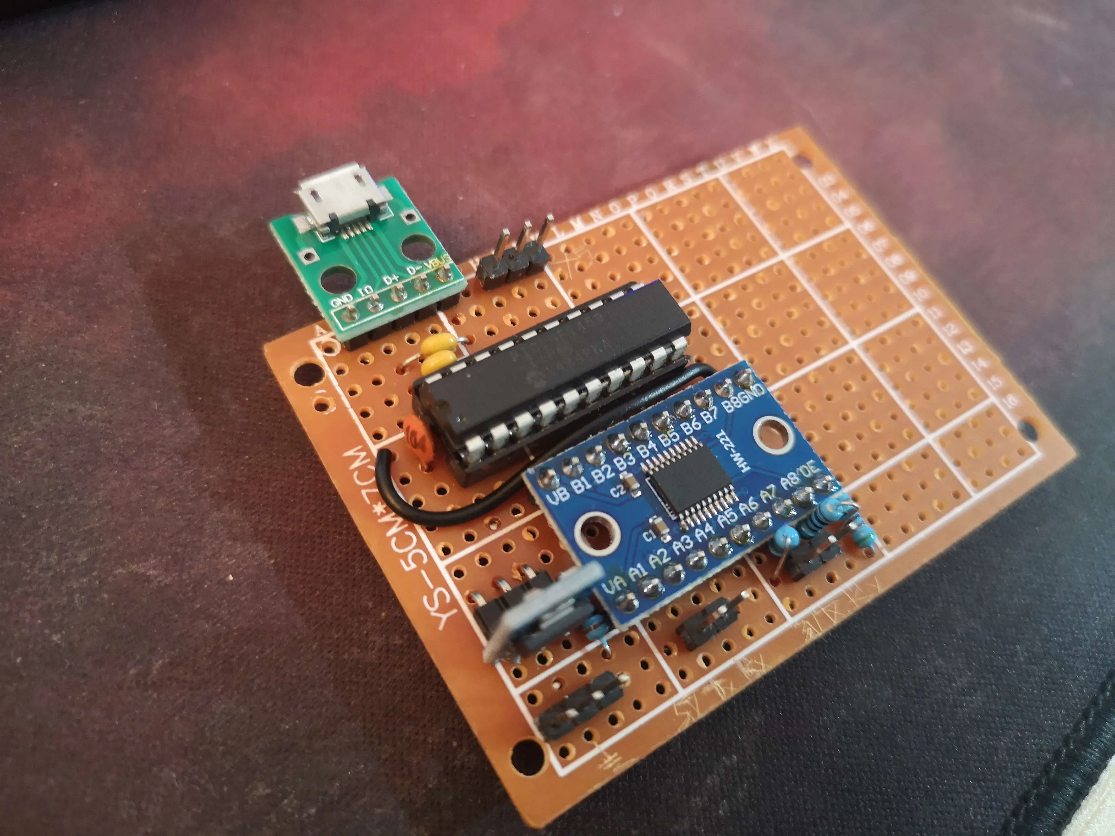
To get a 3.3V rail for the TXB0108 I just used an AMS1117-3.3 regulator board with included capacitors and indicator LED, which was also a nice touch since I wouldn’t need to add my own. All in all, the hardware ended up being very simple as most of the work had already been done on the boards I used. I built up and soldered the circuit directly, without trying it on a breadboard, since I was certain that it would work. I also added 510-ohm resistors to all the input and output lines (which I almost forgot (and forgot to write here as well)).
I unironically love MPLAB and what I do
The software was also quite simple to make, despite some fears I had initially. The PIC16F1459 is an 8-bit microcontroller with only 1KB of RAM, 8KB of flash, and 12MHz of effective execution speed (since the PIC architecture internally divides the clock by 4). I was worried that running an entire USB stack and having real-time UART communication at quite a relatively high speed would be unfeasible, so I began to think about a clever way to go through with the circuit. At USB1.1 speeds, which is what the PIC is running at, the maximum throughput is 12Mbps (megabits per second), however USB CDC is different in the way that it sends 64-byte packets every 1ms. Without any buffering, the maximum possible speed given this arrangement of the UART would be around 8000 baud, with 1 byte per packet being sent and the UART not being buffered – used in blocking, non-interrupt mode. Theoretically, though, with buffering a maximum speed of 64 * 8 * 1000 or 512000 baud should be possible.
Due to a bug in MLA, the maximum size of a USB CDC endpoint is 32 bytes instead of 64, which limits the speed to only 256000 baud. This is quite close to the 115200, but what assuaged my fears was the fact UART is rarely fully saturated, and you probably shouldn’t try to do so either, since it can interfere with automatic error detection. With this, the USB side was finished, having decided to go with the 32-byte sized endpoint. However, a buffer for the physical UART was also necessary, which is where Microchip’s MLA proved to be incredibly useful.
I found out that the UART library already automatically buffers writes in a circular buffer and reads and uses an interrupt-driven system to do so. This makes it completely opaque to the user, while eliminating the need for blocking code. The library also has extensive error handling, which I don’t need but I’ll keep. Since the writes were buffered, I could create a large write buffer, and copy the smaller USB buffer into it by just calling the regular library write function. The write buffer had a maximum size of 64 bytes (which can be made larger through modifying the library), which means it can hold two whole endpoints worth of data. Since UART uses effectively ten bits (one start, one stop and eight data), the actual speed of the UART is 11520 bytes per second, or 11.5 bytes per millisecond. This means that hypothetically the write buffer can overflow, however in practice most programs try to avoid this. With the library automatically writing bytes from the buffer as soon as the UART peripheral finished its previous write, the job of writing bytes from USB to UART was as simple as it can be.
For the reading, there was a read buffer as well, but I found out that adding a custom UART read callback which buffers reads directly to the USB send buffer was much easier and more practical. With a custom index that keeps track of the buffer’s size and resets it after every USB packet transfer, and given the calculation above which shows that reading a 115200-baud stream cannot fill up a 32 byte buffer that empties each second, the read mechanism was even simpler. The total code ended up being around 50 lines, around half of which were empty space – this is it:
#include "mcc_generated_files/mcc.h"

/*
    Main application
 */

static uint8_t readBuffer[32];
static uint8_t writeBuffer[32];
uint8_t wbi = 0; // write buffer index

void USB_MainTask(void)
{
    if(USBGetDeviceState() < CONFIGURED_STATE){return;}

    if(USBIsDeviceSuspended() == true){return;}

    if(USBUSARTIsTxTrfReady() == true){
        uint8_t numBytesRead;

        numBytesRead = getsUSBUSART(readBuffer, sizeof(readBuffer));

        for(uint8_t i = 0; i < numBytesRead; i++){
            EUSART_Write(readBuffer[i]);
        }

        if(wbi > 0){
            putUSBUSART(writeBuffer, wbi);
            wbi = 0;
        }
    }

    CDCTxService();
}

void UART_Read_Handler(){
    writeBuffer[wbi] = RCREG;
    wbi++;
}


void main(void)
{
    // initialize the device
    SYSTEM_Initialize();

    // Enable the Global Interrupts
    INTERRUPT_GlobalInterruptEnable();

    // Enable the Peripheral Interrupts
    INTERRUPT_PeripheralInterruptEnable();

    EUSART_SetRxInterruptHandler(UART_Read_Handler);

    while (1)
    {
        USB_MainTask();
    }
}
Miraculously, despite my hubris, everything worked on the first try. I was able to communicate with my Lichee Nano without an issue. Because of this, I’m planning to expand the USB-UART to accommodate RS485 on the empty board space, which I already have the chips for, I just need screw terminals. I love procrastinating on assignments that I’m already very late on with a test tomorrow in the meantime!