I like music and I like electronics, so mixing music with electronics is something I would presumably like more. Except that I don’t really like electronic music, so the next best mix of electricity and music has to be guitar pedals. For those who don’t know, guitar pedals are small electronic circuits, usually in a box, that take the simple sound output of a guitar and add effects to it, electronically. Proper mixing of these effects form the basis of genres like rock, metal or shoegaze. I was most drawn to guitar pedals due to how large and devoted the online community is, and how freely they share information. Yet, as a high school student with no source of income, buying guitar pedals is prohibitively expensive, particularly the ones I want the most (Strymon Big Sky, 500 euros?!). Thus, I decided to make my own.
The theory behind the chorus effect
As an owner of the famous Yamaha DX7 synthesizer, I naturally love the sound of electric pianos. The only thing that sounds better than an electric piano, is an electric piano with reverb and chorus. Naturally, then, I decided to build a chorus guitar pedal and use it on my synthesizer, because you can do that too. Naturally, as well, the chorus effect comes out to be one of the more complicated ones. Intuitively its operation is simple – you take an original signal, which can be modeled as a sum of sinusoidal functions, modulate its frequency with a low frequency oscillator, and combine the modulated sound with the original. Mathematically it can be represented as sin(x) + sin(x + sin(a)), where sin(x) is the original sound wave, and a is the LFO frequency.
Where theory meets reality
However, an issue here arises where to have the sound play in any point in time, if sin(a) is negative, then we will need to know what sin(x) (the sound input, not necessarily just sin(x)) used to be, and if it is positive, we need to know what it will be. This requires some sort of memory, and in terms of circuits it can be done in two ways – analog or digital. The analog way, as it was done in the 70s and 80s, requires Bucket Brigade ICs, examples of which are the Panasonic MN3005 and MN3008. These were essentially just massive arrays of capacitors arranged as a shift register, and one could shift in and out analog values. This worked well, however those chips have long been discontinued, and are quite annoying in the way that they require a -15V supply, despite most guitar pedals using only 9V or even 5V. They also require support circuitry to generate a clock, and are expensive to get nowadays as well.
Going digital (screw the analog purists!)
Thus the other remaining choice for the guitar pedal enthusiast is to go digital. Here, there are two ways to go about this as well. Either one can choose to use an MCU/DSP with an audio codec chip, as many advanced modern guitar pedals do, or get a dedicated chorus effect chip. The first choice is the most flexible by far and has yielded some of the most advanced and best-sounding chorus effects, however it also requires clever algorithm design and is limited to hard-to-find SMD parts, most often high-end Analog Devices DSPs (like in the Big Sky). I, as a high school student without a budget and any available PCB manufacturers with reasonable prices nearby, will avoid this and head for the last remaining option.
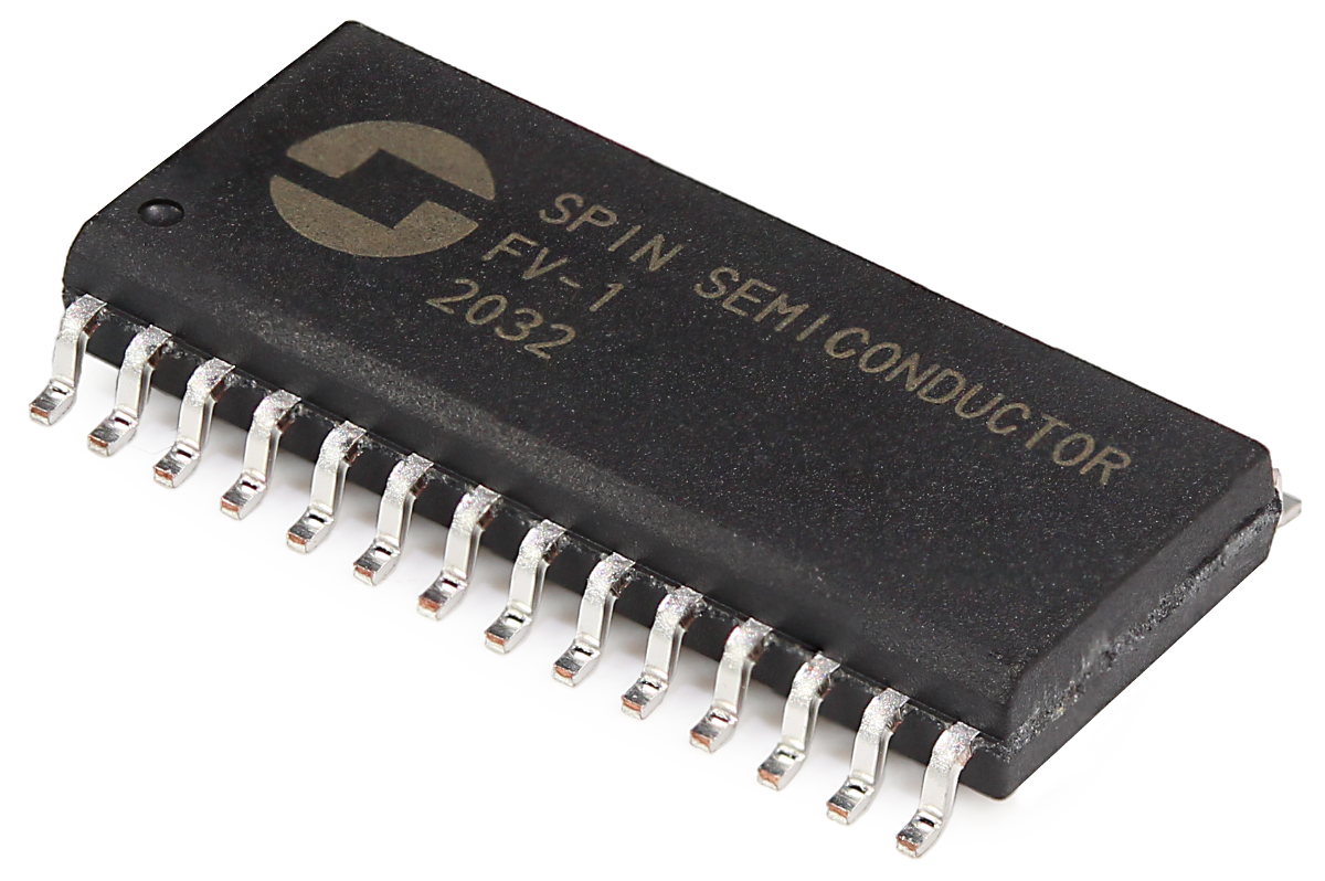
There exist two famous chorus ICs – the Princeton Technology PT2399 and Spin FV-1. The latter is actually a multi-effects chip with a programmable processor and codec included, however it’s quite expensive, only in SMD and hard to find – since it’s out of production. The PT2399, also out of production, is available in limitless quantities for extremely low prices, and best of all, in DIP format. Its datasheet is quite poor, though, without many explanations on the internal operation of the chip, however many hobbyists and engineers on the internet have managed to crack it open and analyze it, most famously this ElectroSmash article.
Still, even when knowing its internal workings, the datasheet or engineer’s way may not actually always yield the best result – in this case, the most famous PT2399 DIY design actually uses the chip in a way not described by its datasheet, which I will not describe here, rather just link the associated famous forum thread on diystompboxes.com, the most famous guitar pedal circuit design and analysis website. The design I built was a modified version that’s considered one of the best simple PT2399 pedals around.
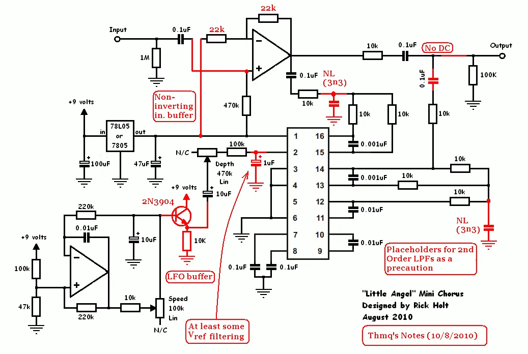
The build
As I cannot afford to have circuit boards shipped from China (the only shipping offered is FedEx and DHL, both 50$+), I build everything on perfboard, which takes a long time and looks quite ugly, but it has a homemade charm to it. Due to the impossibility of finding proper enclosures, I decided that the pedal build would be just a simple bare PCB. My build process for perfboard circuit boards is very simple – I follow the original circuit schematic topology, figure out the best orientation to take up the least space, identify groups of components, and then place the components, bend their leads and tie them to all necessary connections, and finally solder them together. All in all, this process takes 20-30 minutes for a design such as this. The soldering takes around 1-2 hours and this involves adding in extra wires where necessary and finding the shortest non-overlapping places for leads to go through. I try to minimize the number of extra wires I add, as they are bulky and can make the design hard to follow and repair.
Since the design was built without an enclosure, and I am not a guitarist, I decided to go with 3.5mm audio jack breakout boards instead of the usual 6.35mm, and placed the boards in a female socket, so that if I ever decide to add an enclosure I can easily connect external wires from a connector to the sockets. For the 9V input I decided to go with the ubiquitous guitar pedal 9V 6F22/LR22 battery. This results in the least noise, even though that wouldn’t be a problem in this design as it uses a 5V regulator with large capacitors anyway, and the only noise that would result would be from the digital switching in the PT2399 itself. I scavenged an old 9V battery connector from a broken clamp multimeter and added an input diode to protect against accidental reverse brushes with the battery. In retrospect, I should also have added a small-value current limiting resistor before the large capacitors, as is often added in guitar pedals. This both forms a low pass filter to limit noise further and provides slight added protection against reverse voltage.
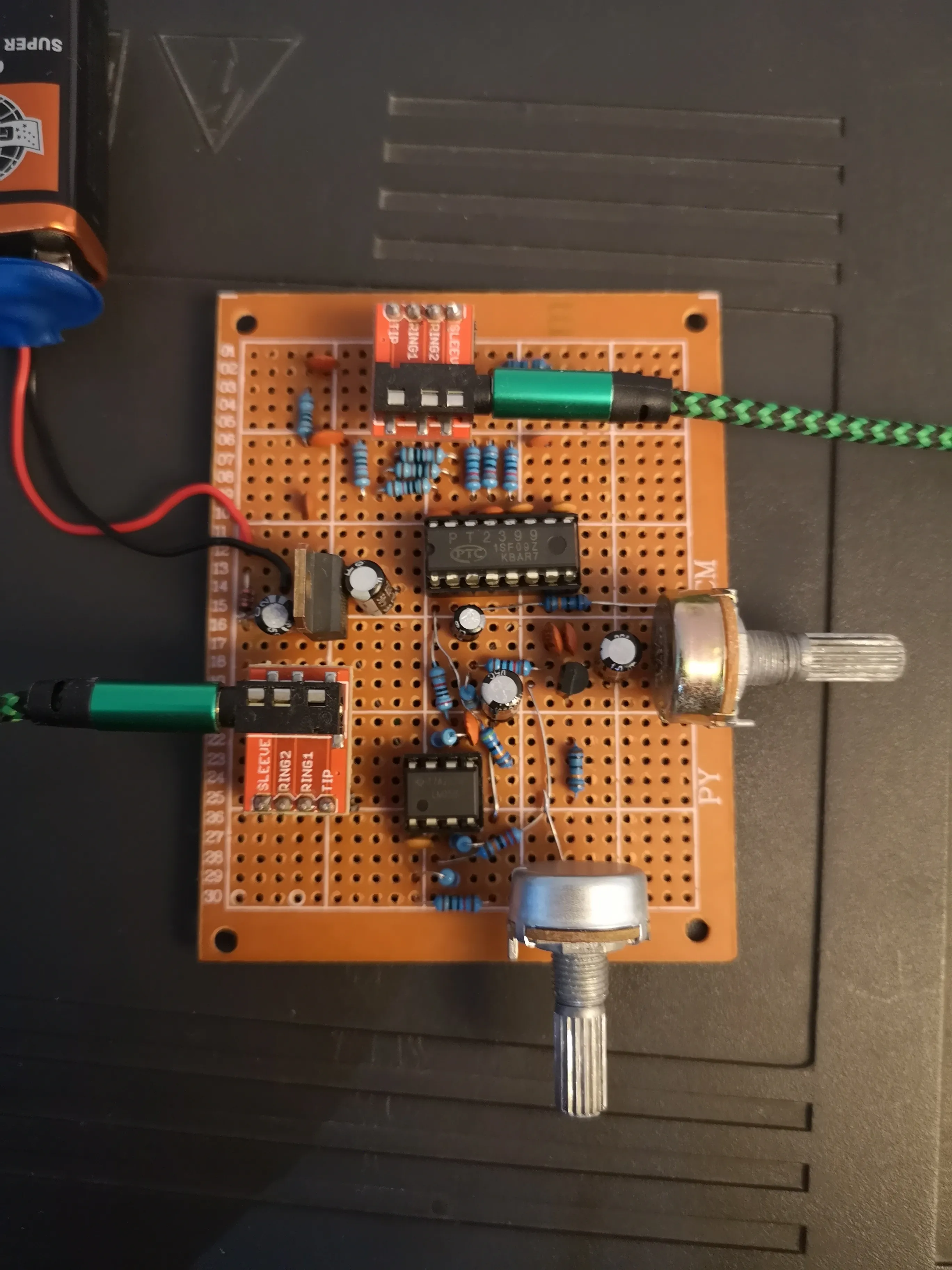
With the build finished came time to test it. Surprisingly, everything worked from the start. The pedal worked almost flawlessly, though it did lower the signal level significantly and required extra gain from my audio interface. Still, despite the extra gain, no noise at all was audible, which was quite incredible to me and a testament to the good design of the schematic and my star grounding scheme. Attached below is an audio sample, the difference isn’t very obvious but it does add a nice flavor to the timeless DX7 E-piano, which is all I ever wanted.
The DX7 E-piano without the chorus effect and with slight chorus effect:
The DX7 E-piano with the chorus effect on the maximum setting: