8051 woes
The 8051 microcontroller, in its stock configuration, does not contain an inbuilt ADC. For modern microcontrollers, this is quite a big issue, as ADCs are necessary for a majority of microcontroller tasks. For the 8051, this task is usually relegated to an external ADC chip. As I’m currently making tutorials for programming the 8051 in C I wanted to make one where I show how to interface it with an ADC. Even though theoretically this should have been an easy task, and it was, the journey to there ended up being interesting enough to require a blog post of its own.
Issues of logistics
The first and most obvious issue would be getting the chip itself. Due to the limitations of the supply of chips in my country, I had to be a bit more proactive in obtaining an ADC, so when my parents went on a trip to neighboring Serbia, I knew that was my time to strike. I looked at the two electronics stores of the city they were passing through and made sure to find an ADC which would be compatible with the 8051. This mainly meant that it was single-supply and had a parallel bus. Dealing with non-UART protocols on the 8051 is a hassle since the base chip doesn’t contain any of the infinite supplies of modern peripherals one is given when dealing with something like a PIC or STM32. However, the 8051 is excellent at shifting data around in a parallel bus, just like its 8-bit microprocessor ancestors.
A perfect fit!
The search ended up being somewhat easy since there aren’t many supplies even in the neighboring countries. Eventually, I ended up settling for the ADC0804 which is common enough and very convenient for interfacing. The parallel bus is 8080-compatible, and the interfacing can be described in one sentence – watch me do it: set WR and CS low, set WR and RD high, wait for interrupt, pull down RD, and you have your data (after which you set everything high if you want more). Interestingly the chips this ADC was made to interface with (Intel 8080 and Motorola 6800) were made in 1974. That means they’ll be 50 years old soon!
Setup and info
Also interestingly, the ADC doesn’t use an external clock for internally clocking its conversions (it’s an SAR ADC), meaning that the clocking has to be manually set up using an RC oscillator. Unfortunately this also results in an abysmal maximum speed of 10KHz, however for most purposes this is good enough. My main idea was to eventually be able to connect a thermistor to it, and that would be more than ideal. Any sort of faster sampling would likely require some processing which the 8051 is slow at anyway. I wrote some code to simply sample the ADC and give a raw result through UART, so that I could verify the code is working. I connected the negative reference to ground and the positive reference to a resistor divider from VCC, essentially giving me half the supply voltage. Given that both resistors have 1% tolerance and there was no current draw to increase the heat and change their resistance, this shouldn’t have resulted in any instability. Now did it…?
Testing the ADC
I decided that the best way to test my ADC was to use the amazing Arduino Serial Plotter, which is a perfect little applet that turns any continuous numerical output into a plot, which can even be used as a proto-oscilloscope if needed. Luckily that is exactly what I needed, so I connected up my circuit, using an Arduino Uno as a UART-to-USB bridge, as my FT232RL is still broken. I found out that I don’t even need to do a SoftwareSerial passthrough, rather I read that if you connect the Arduino’s reset pin to ground, the ATMega328 will never even start up and will leave the hardware UART pins (which are normally used for the Arduino hardware serial) available for external use. Just be careful when connecting, as the TX on the board stands for the TX of the ATMega328 itself, and it is the input to the onboard UART-to-USB converter, while RX is the output. Once I connected the 8051’s TX to the board’s TX, I saw a lovely stream of data that was approximately right!
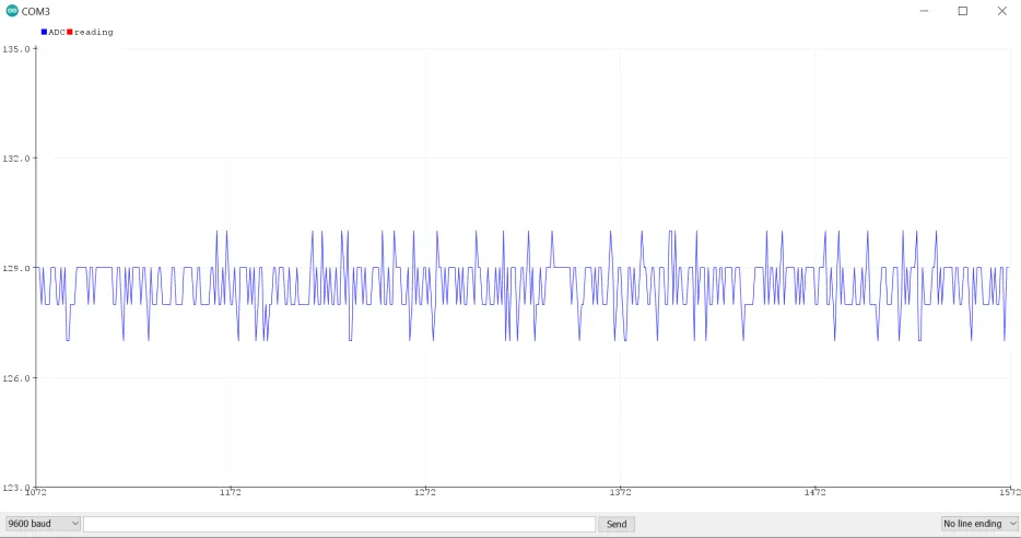
I was elated that my code worked on the first try, however my excitement died down once I saw how unstable the output was. Here began my true journey of discovering how to improve the ADC’s output and make it stable enough so that you can trust your measurements. This first result told me that the ADC output was unstable by +- 2 bits, and from there the ideas to fix this came in.
The first issue that the datasheet recommended fixing was adjusting the VDD/2 voltage reference with an external voltage divider buffered with an opamp. I got one of my ROHM Semiconductor, somewhat vintage quite nice low noise BA15218 opamps and connected it as the datasheet suggested. This only slightly fixed the unstable output, and I deemed it unimportant enough to screenshot.
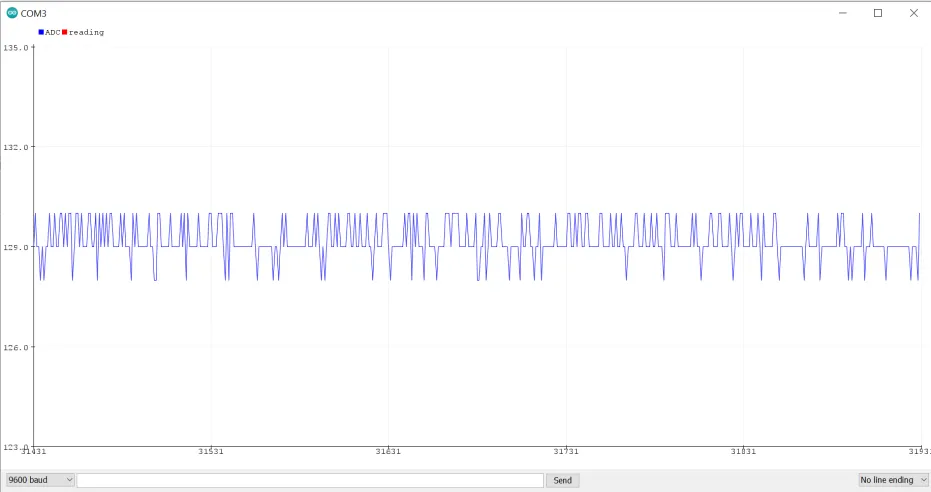
The second issue was the fact that I powered my breadboard circuit through the Arduino Uno, which meant that the power was coming from my PC extremely noisy USB port. For this I went with my DIY external bench power supply, but the noise persisted, since the power supply is just a fancy buck converter which is noisy as well. To fix this I used an idea that I’d thought about, which was to use a higher voltage output and then use a classic 7805 linear voltage regulator to make the output smooth. I then added a large 100uF electrolytic capacitor between the higher voltage output and ground and a smaller 22uF one between the 5V rail and ground. Then I added a second 22uF right in front of the ADC0804 for any power hungry surges, and then followed that up with adding 100nF ceramic capacitors between VCC and ground next to every chip, as is tradition. Doing this helped the stability a lot, lowering it down to +- 1.5 bits, as seen in the screenshot below:
The next step to improving the output would be looking at the input I was putting in. I realized that since the 7805 was being fed by a high frequency buck converter, a lot of that noise is likely to pass through. Furthermore, the 7805 introduces some noise itself, it’s not perfect (despite what many would say). This brought me to my next idea of low pass filtering the noise out. I got out an online passive RC low pass filter calculator and using the two components next to me, a 10K resistor and 100uF capacitor, calculated a low pass frequency of ~0.15Hz, which for my completely static DC signal would not be an issue. For any higher frequency sampling I’d replace the 100uF capacitor with a 1nF capacitor to give a cutoff frequency that corresponds with the ADC0804’s max sampling speed. After filtering the result this way, I saw a dramatic improvement:
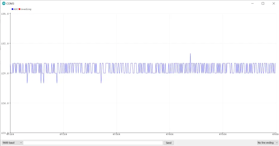
Even though the results are still noisy, the noise is less common and I would say that the noise has been reduced to +- 1 bit. I was almost satisfied fully with this result, but I knew that it was possible to do even better. The current setup as it was existed in a pseudo-active low pass filter, with the passive filter being followed up with a unity gain opamp stage. It was at this point that I also replaced the two resistors with a potentiometer, for no reason other than I liked to spin the potentiometer and see the plot move around. Once I spun it to 2.5V I got the same plot as before and it was time to get serious and fix the noise. I decided to use one of the opamp tricks I knew to reduce noise and added a 100nF feedback capacitor between the output and the positive input to reduce the bandwidth (which I don’t need) and lower the noise. It was at this point that I also replaced my low noise BA15218 with a common LM358 to see if that did anything to the input. This combination of changes led to the noise improving even more and now one could even say that it is somewhat stable:
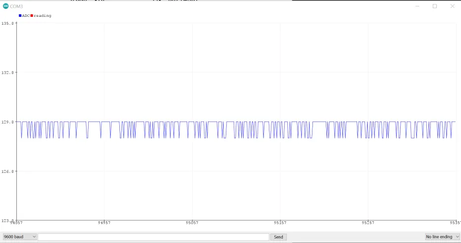
However, I am looking for perfection. So far, I have low pass filtered the input to the opamp, done compensation, spun a potentiometer precisely and made a fancy voltage reference. The final idea I had, to fix the ADC once and for all, had to be genius, had to be something nobody would ever think of, it had to be something that would change everything. I remembered that I read once that ADCs don’t like too high output impedances, but they don’t like no output impedance at all either. The opamp in unity gain represents a perfect buffer with zero output impedance, which I presumed the ADC wouldn’t like. Thus the extremely complex solution came down to connecting a 10K resistor between the opamp output and the ADC input:
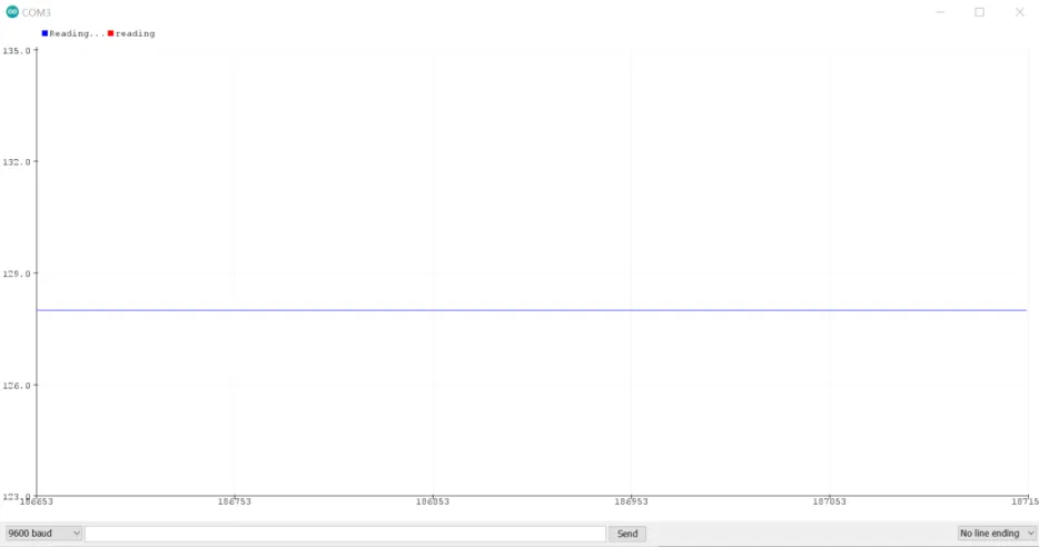
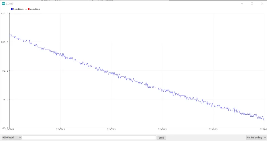
Yes! YES! This was beautiful and absolutely worth the extra hour and half spent on optimizing the circuit and reading about lowering noise. This made me overjoyed and is probably the first somewhat serious attempt at getting an accurate result from a measurement, which is something I used to be terrible at. Just for fun, I disconnected the potentiometer from the breadboard, so that the capacitor was the only powered thing connected to the opamp which fed the ADC with data. From there I got this graph, and I was surprised at how fast the capacitor was depleting. I’d have expected longer from a capacitor of that… capacity:
To summarize, this mini project taught me a couple of things. Firstly, it is usually worth it to go for a proper result instead of being satisfied with a mediocre result. Still, experience has taught me that one shouldn’t worry too much about being perfect as well, there must be a balance between the two. In this case, going further was worth it and enabled me to have more precise and stable ADC results than I’ve ever seen. Secondly it affirmed something I’d read in the book Atomic Habits – small optimizations add up quickly and result in a large total optimization. In this case, I went from an unstable output that cut down my accuracy by a lot (effective 6 bits from an 8 bit ADC) to a perfectly stable straight line that would make most nerds happy. I know it made me happy, at least.