The main issue
As a high school student in a country with extremely limited import capabilities, my choices of equipment for my electronics hobby must be necessarily modest. This is exacerbated by the fact that the used market here is nonexistent. Thus most of my equipment, basic items like a multimeter or soldering iron, is either outdated or low budget and likely unsafe. Getting into the territory of more advanced tools, like an adjustable DC power supply, the situation gets even more dire. The cheapest power supplies available are either ancient and probably hazardous, or new and heavily marked up (~3 times MSRP). In this case, Aliexpress comes to the rescue! I researched about different power supplies and concluded that at the time, a DC-580 buck converter power module would be my best choice.
A pleasant surprise
I ordered one for the equivalent of 10$, and a month later it arrived well-packed and safe, though it took a while for it to come. The quality of the construction surprised me, the inductors seemed excessively well-sized and the capacitors had a voltage capacity that would be higher than anything the module would have to face. I felt glad that this module turned out to be a good investment, hoewever, unfortunately, here my first issue faced me – this module is not a standalone power supply. To be honest, I knew that when I bought it, however at the time my thinking was “I’ll figure out a solution when it arrives”. Well, it arrived, and I had to think of a solution.
Powerful problems
The main issue was that this module is a buck converter, meaning that it needs a different power supply with a constant voltage to power it, and it’s only able to output a voltage that’s less than the voltage the power supply provides it. This meant that I needed another power supply, one of sufficiently high voltage. My requirements were for the buck converter module to produce at most 15V, which meant that the input power supply would have to be at least 17V, to account for potential losses of the voltage from one power supply, to another, and then to a buck converter. The solution actually came out to be surprisingly simple, and it came in the form of a laptop charger. Invariably a power supply, laptop chargers usually output a voltage that comes out to around 19.5V, and a maximum power output of 65W. Since I never planned on pushing the module above 15V, and much less above a couple of watts, a laptop charger would prove to be a perfect option.
Recycling to the rescue!
Since I repair laptops on the side, I had a myriad of laptop chargers, and I just picked the first one that I found – an old Toshiba charger. Next, I had to somehow gather a connector for the plug of the charger to connect. Luckily, the charger had a standard connector size of 5.5mm x 2.1mm (meaning I could use it for an Arduino if I don’t draw much power), and it was left to find a fitting DC jack. Since the nearest electronics store is 40km away, with heavy markups, and I have no way to travel, scavenging remained the only option. Initially I though I’d have to scavenge one from an Arduino, the idea of which didn’t excite me much. However, looking at my pile of broken electronics, I found an old broken battery charger which indeed had the same size DC jack. A few minutes of desoldering gave me the perfect-sized power jack I needed for my power supply.
Lack of parts strikes again
Unfortunately, here my project came to a stop. The last part of my DIY power supply project would be to put it in an enclosure. I did the necessary measurements and sizing, however I had neither the power tools needed, nor did any of the electronics stores in the country stock an enclosure for an appropriate price. The only one available came out to be many times more expensive than the module itself, which is obviously against the idea of the project, and is beyond my monetary capabilities. However, in the spirit of the IB program, I sought a global solution. Not Chinese, since that wouldn’t be ecological, which goes against the spirit of the IB learner profile, which left the only choices to be neighboring countries. For the lucky country to face my newfound IB learner disposition I chose Serbia, where my parents had a trip organized to. I gave them the location of the store and the plastic enclosure they needed to buy, and some time later I received two plastic enclosures for the equivalent of 2$.
First foray into construction
With all the parts in hand I went to place the power supply in the enclosure. I thought that the enclosure was ideal, as I had calculated the sizing properly so that the fit would be perfect. I was going to simply place the power supply in the enclosure, and because of the way the enclosure was constructed and the power supply was built to snap into place, it was going to just work. However, since this was the first time I’d done anything involving mechanical construction, I didn’t account for tolerances at all. Because of this, the power supply didn’t fit. What worsened the situation was the fact that I had no tools that could shave the few millimeters needed to make it fit, while those few millimeters were the David to my Goliath.
Second board construction
Nevertheless, I ignored that issue and decided to work on another issue, which was placing and holding in place the DC barrel jack connector. I took one of those ubiquitous Chinese prototyping boards made out of wood, and using a pair of pliers managed to create holes wide enough for the thick pins of the connector to fit. I soldered the connector in and was surprised at how sturdy it came out to be. Next, I decided to place a filter capacitor, a large electrolytic one, to filter the incoming DC from the laptop charger. The charger is a switching power supply, which necessarily comes with excessive noise if not filtered properly, and I doubt that a forgotten laptop charger would have proper filtering, since it gets regulated down to various voltages anyway. In this case I didn’t want much noise to get to the power supply since it would pass through to the output. For the filter capacitor I chose an old Rubycon 680uF80V capacitor I had salvaged from an old router, which despite the 20 years of age is still a Rubycon, therefore excellent capacitor. For the traces, I used a tip I had read online. I kept all of my used desoldering braid, now thick with solder, as a high current trace. This also had the benefit of being easy to solder, while being made up of copper and solder, which are both excellent conductors.
Wires?
However, when it came to connect the power input board to the power supply, an issue came up. The power supply, unfortunately, uses screw terminals for connection with input and output power. Screw terminals are a terrible choice for anything permanent, and this is no exception. I gave some thought to removing the screw terminals and soldering a wire from board to board directly, however this would mean that the power supply module would be permanently stuck to the power input board, which I didn’t want. I chose to skip any sort of invasive solution and decided to work with what I was given – screw terminals. I only had 24AWG aluminium wire, which due to the relatively high voltage and low current I needed for the input voltage wouldn’t be an issue. The wire had ~28mOhms resistance, which at 20V1A gives a power loss of only ~0.13%. Using the screw terminals on the power supply, I connected both boards, soldering the wire directly to the power input board, with a thick blob of solder directly onto the desoldering braid traces. I verified that the connection was sturdy and went on to the issue of mechanically connecting the power supply and the power input board to the plastic enclosure.
Power tools?
Here the issue of my lack of power tools came to haunt me again, as the scavenged screws I had prepared and carefully sized to connect decided to simply break. They broke and I couldn’t get them out, which confused me and I was stuck on the problem for a few minutes, thinking on what to do now that I couldn’t make the connection between the boards. Regretfully, the solution came out to be the solution for all mechanical related problems – excessive amounts of (electrical) tape. Using creative electrical tape placement, I secured the power input board to the enclosure, and then using even more electrical tape I sealed the enclosure completely. Surprisingly, this came out to be a sturdy solution and no amounts of careful mechanical impact testing could even move the boards. Repeated reinsertions of the charger to the DC barrel jack didn’t make the board move at all, which made me conclude that I had managed this issue well, albeit crudely.
Finish
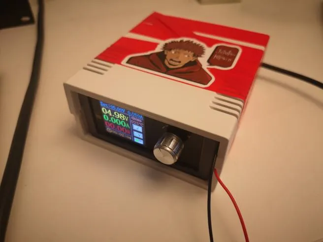
Finally, I yassified the power supply with an anime sticker and photographed it with an Instagram filter, to obtain the following results: